
TM 1-1500-204-23-11
(a) Remove dirt, grease and aircraft luids
above dimensions using the proce-
from repair area as described in para-
dures described in paragraph 5-6f.
Use the ply orientation speciied in
the system speciic technical man-
ual.
DO NOT use oil or oil based materials
as NDI couplants on advanced composite
components. Use only water or water based
materials. Disbonds may result and loss of
structural integrity may occur.
(b) Deine the extent of the disbond using
NDI according to paragraph 5-10 and
the system speciic technical manual.
Lay out the damage as described in
(c) Remove NDI couplant by wiping with
clean, water moistened wiping cloth.
(d) Damage Removal.
Cut through the rib and the dam-
1
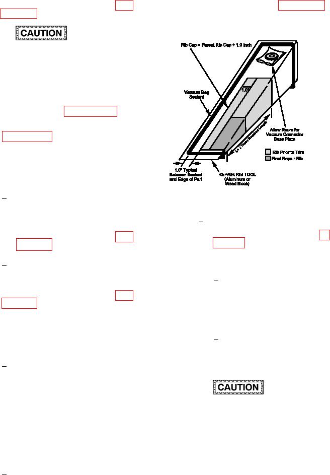
Figure 7-48. Repair Rib Layup and Tool
aged skin on both moldline sur-
faces along the damage layout line
Prepare the Repair Rib Tool. If a
3
deined above. Use a 90 degree
tool is not available, fabricate a tool
router motor and a diamond coated
from a wood block as shown in ig-
cutting wheel as described in para-
ure 7-48. Use an identical undam-
aged spare part to obtain dimen-
sions for fabricating tool.
Remove damaged rib and skin
2
material.
Lightly sand the surface
a
of the tool to remove any
(e) Remove paint from skin in the repair
protrusions. Wipe sanded
area by sanding as described in para-
area with a clean, dry wiping
cloth to remove sanding
residue.
(f)
Vacuum and wipe with clean, dry wiping
cloth to remove dust and debris.
Tape a layer of release ilm
b
over the layup tool. The
(g) Fabricate Repair Rib.
release ilm should be several
inches larger than the largest
Cut one piece of dry woven cloth
1
ply.
large enough to provide enough
plies of the required ply orienta-
tion. The required repair rib length
needs to provide the required over-
lap between the repair rib and the
Reduced strength will result if the incorrect
parent rib. Make the rib twice this
mix ratio is used, if an excessive amount
required length to allow for trim-
of air is introduced into the adhesive during
ming and for fabrication of two rib
mixing, or if mixing is inadequate and may
spacers. Size rib caps 1.0 inch
result in loss of structural integrity.
wider than parent rib cap for trim-
ming.
Pressure must be applied to adhesive within
the pot life of the resin. For ambient temper-
atures in excess of 90 F, decrease this time
Fabricate a cutting template for
2
by 50%. An unsatisfactory repair will result
repair rib plies based upon the