
TM 1-1500-204-23-11
a. Edge Damage Limitations. Edge damage lim-
(1) Facilities, Equipment and Materials. The
itations are noted in the speciic weapon system
following equipment and materials are required: Vac-
technical manual. The following are limitations spe-
uum Cleaner, HEPA Filter, Dual Action Sander or 90
ciic to fasteners.
degree die-grinder and sanding mandrel, 90 Degree
Router Motor, 20,000 RPM, 0 Degree Router Motor,
20,000 RPM, Overhose Assembly, Router Holder,
(1) For edge damage that affects fasteners,
Sanding Disks, 80, 150 & 180 Grit, 1.0 & 2.0 Inch
redrill holes and replace with proper grip
Diameter, Sanding Disk Holder, Cutting Wheel, Dia-
length fasteners. See paragraph 7-7 for
mond Coated, 80 Grit, 1.0 Inch Diameter, Heat Blan-
redrilling fastener holes.
ket, Temperature/Vacuum Controller, Scissors, Adhe-
sive Comb, Silicon Carbide Abrasive Paper, Flash
(a) Damage limitations across any two
breaker Tape, Wiping Cloth, Spatula, Adhesive, Liq-
adjacent zones are provided in the sys-
uid (See System Speciic Technical Manual), Adhesive,
tem speciic technical manual.
Paste (See System Speciic Technical Manual), Vac-
uum Bag Repair Materials Kit, Patch (See System
(b) Fabricate external, iller, and internal
Speciic Technical Manual), Dry Woven Cloth (See
patches per system speciic technical
System Speciic Technical Manual), clamp, temporary
manual repairable damage table.
fasteners.
b. Edge Damage Rebuild. This repair is applica-
(2) Edge Damage Rebuild Procedure.
ble when the damage limitations for paragraph 7-8(g),
resin injection of edge delamination repair, have been
(a) Remove dirt, grease and aircraft luids
exceeded. A scarf joint is incorporated to reduce
from repair area as described in para-
inner moldline protrusion for it up with mating part
surfaces. If it up is not a consideration, the scarf
joint is unnecessary and should not be used. Edge
damage requiring rebuild in other than lightly loaded
areas (such as hinge locations or load bearing fas-
tener holes) may require engineering disposition and
DO NOT use oil or oil based materials
generally is forwarded to depot for repair. This repair
as NDI couplants on advanced composite
procedure is not necessarily applicable to a partic-
components. Use only water or water based
ular weapon system. The applicability of this repair
materials. Disbonds may result and loss of
depends upon additional factors such as loading con-
structural integrity may occur.
ditions and laminate thickness. Consult the system
speciic technical manual or engineering for further
(b) Deine the extent of the disbond using
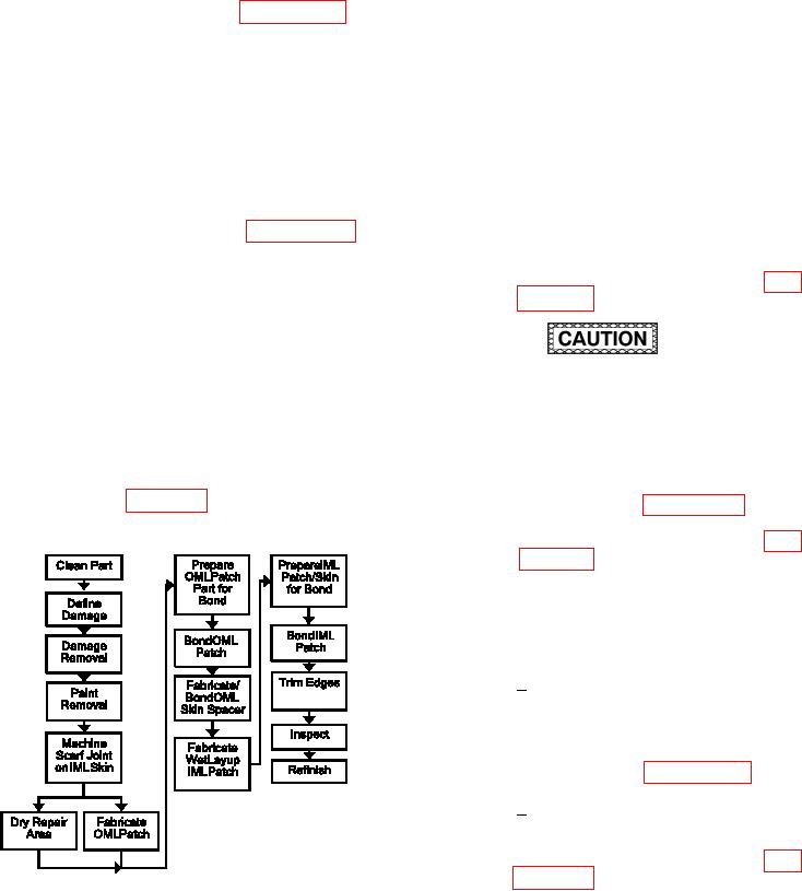
guidance. Refer to igure 7-45 for the Process Flow
NDI according to paragraph 5-2 and the
Diagram for Edge Damage Rebuild.
system speciic technical manual. Lay
out the damage as described in para-
(c) Remove NDI couplant by wiping with
clean, water moistened wiping cloth.
(d) Damage Removal.
Cut the damaged skin on both
1
moldline surfaces along the dam-
age layout line deined above using
a 90 degree router motor and a
diamond coated cutting wheel as
described in paragraph 6-4.
Remove damaged skin material.
2
(e) Remove paint from skin in the repair
area by sanding as described in para-
Figure 7-45. Process Flow Diagram for Edge
(f)
Vacuum and wipe with clean, dry wiping
Damage Rebuild
cloth to remove dust and debris.