
TM 1-1500-204-23-11
d. Deinitions.
(8) Trace the orientation marks and perime-
ter markings onto the template ilm. Also
include an outline of any damage.
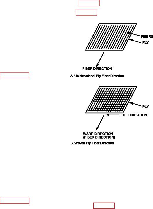
(1) Lamina. The lamina or ply is the single
layer in a laminate. Fibers in the ply are either
5-6. PLY ORIENTATION. To ensure the ibers in an
unidirectional (all ibers in the same direction) or
advanced composite laminate perform their function of
woven into cloth.
carrying load and providing part stiffness, it is essential
that the ibers (plies) be properly oriented within the
(2) Lamina Fiber Direction. The iber direction
laminate with respect to the 0 iber direction. In the
of a unidirectional ply is coincident with the ibers in
same way we would expect a map to tell us which
that ply (igure 5-8, View A). For woven cloth, the
way is North relative to the features on the map, we
iber direction of the ply is the warp direction of the
expect a part drawing to tell us which way is "0" or
weave (igure 5-8, View B).
"0" on the part itself.
a. Warp Fibers. When using unidirectional tape,
orienting each ply simply means lining up the ibers
in the ply with the orientation speciied, be it 0, 90,
+45, -45, etc.
b. Woven Fabric. When using woven fabrics
which have ibers in both the warp and ill directions
we must understand that only the warp ibers are
used for orientation purposes. The warp ibers (yarns)
are those running the entire length of the roll of fabric
covered in greater detail in paragraph 4-3. In addition
the individual plies in a laminate must be placed in
the proper stacking sequence to ensure the required
laminate mechanical properties are obtained.
c. Determining Ply Orientation. "Reading" the
laminate is required when structural technical data
showing ply orientation at the damaged area is not
available. While the light relecting from a sanded
surface can reveal the presence of plies of different
orientations, accurately determining the directions of
these plies is fairly dificult. The use of a magnifying
glass (8 to 12 power) is helpful. Using a needle to
pick out individual ibers should be used only as a
last resort. The ply direction in a scarfed surface
can also be read when the damaged material is
being removed; that is, the removed pieces can be
Figure 5-8. Ply and Ply Fiber Direction
split apart to observe the direction of the ibers. A
group of plies lying together in the same direction
(3) Laminate 0 Degree Fiber Direction. The 0
are not easily distinguished, but the length of the
degree laminate iber direction is usually coincident
scarf through each group of plies will reveal the
with the primary load direction of the part or patch.
number of plies in the group. Wet sanding with 400
rit sandpaper eases the reading of the ply orientation.
(4) Ply Angles. The angle of each ply or lamina
A reference system will be necessary to identify the
represents its orientation in degrees between the ibers
actual ply layup of the laminate and subsequently the
in that ply (lamina iber direction) and the 0 Fiber
repair plies. An explanation of the standard reference
direction of the (laminate) part or patch. A 90 degree
systems and notation is in paragraph 5-9. Document
ply is shown in igure 5-9, View A.
the ply and reference orientation.