
TM 1-1500-204-23-11
Lightning strike protection (aluminum or copper
mesh, or aluminum foil) shall never extend
into the area under the repair patch. Loss of
structural integrity may occur.
g.
In order to ensure optimum strength, repair plies
should be bonded only to the laminate substrate.
Composite structures often incorporate an alu-
minum foil, or an aluminum or copper mesh
below the paint and primer. If EMI/lightning strike
protection is present, it must be removed using
240 grit or iner abrasive paper or Scotchbrite
pad. Removal of EMI/lightning strike protection
should extend approximately 1/4 inch beyond
the largest repair ply.
h.
Vacuum paint removal area to remove sanding
dust. Wipe area with clean, dry wiping cloth to
remove remaining sanding residue.
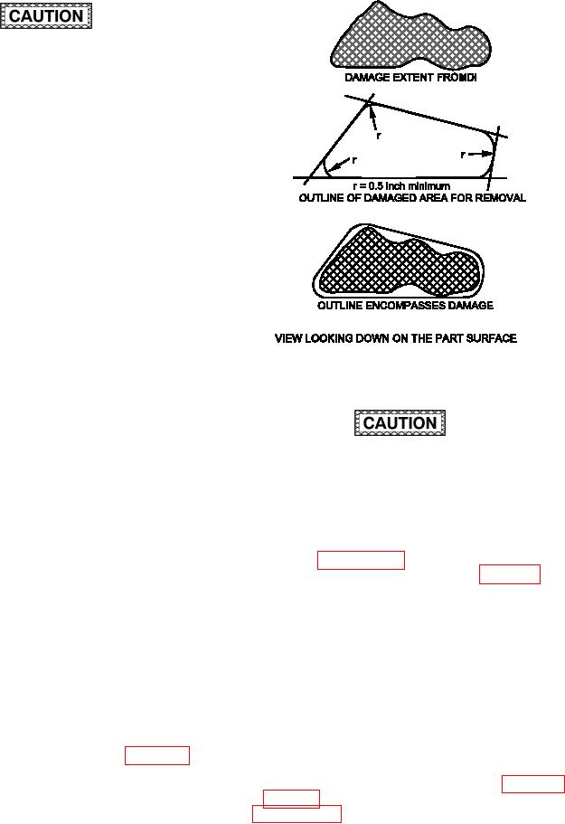
6-4. DAMAGE REMOVAL PROCESS. Damaged
material must be removed to sound material to affect
a structural repair. This means that damage must
Figure 6-2. Damage Outlining
be removed along with a minimum amount of good
material. First, use NDI to determine the damage
extent. Then, determine the cutout shape for remov-
ing damage. A circle is the most practical cutout
shape for damage; however, large damage often
To avoid causing additional damage during
cannot be conined to a circle without removing an
the damage removal process, use the correct
excessive amount of good material. Cutouts required
cutter type and the correct cutter feed/speed
to remove large areas of damage may take any form
for the composite material being machined.
but should be a simple geometric shape which has
straight lines and smooth tapers and radii on the
NOTE
damage boundary. However, maintain generous radii
Refer to paragraph 6-8 for machining proce-
at the cutout corners to prevent excessive stress
dures for composite materials and Chapter 4
concentrations and the resultant overstress of the
for a description of the equipment used for
repair joint. The cutout radius shall not be less
machining.
than 0.5 inch. When outlining the damage area,
use a permanent ink marker on light colored painted
a. Damage Removal Tool Selection. Tool selec-
surfaces or a white pen on dark surfaces. A correct
tion for damage removal is dependent on several
damage outline encompasses the damaged area and
factors. Material type, damage size, depth, and
a minimum amount of good material while maintaining
cutout shapes all affect tool selection. For partial
the minimum required cutout radius. For noncircular
depth damage removal, use a dual action sander or
damage, use a straight edge to draw straight lines
grinder with an abrasive disc. Full thickness mate-
on the damage surface which will encompass the
rial removal requires a faster method of composite
damaged area as indicated by NDI. Connect the lines
machining. The most common of these tools are the
using a circle with a radius not less than 0.5 inch.
Kett saw, die grinder, and high speed router. In many
A typical damage outline is shown in igure 6-2.
cases a combination of different tools is the most efi-
cient method for removing material. See Chapter 3
and table 6-1 for information on speciic tools. Refer
to paragraph 6-8 for machining procedures for com-
posite materials.