TM 1-1270-476-30
6-21
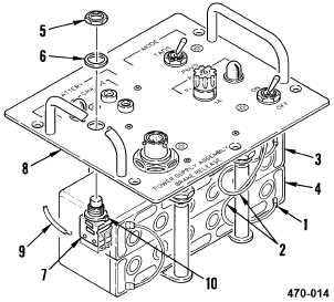
6-4. BRAKE RELEASE POWER SUPPLY ASSEMBLY REPAIR (cont)
g. Position switch (7) in control panel (8) with
alinement key (12) in alinement hole. Install
nut (5) and washer (6) on switch (7).
h. Solder two wires (2) to terminals of
batteries BT1 (3) and BT2 (4) and remove
tags.
i.
Slide insulation sleeving (1) over terminals
of batteries BT1 (3) and BT2 (4).
j.
Have installation inspected.
k. Install control panel assembly (1 above).
END OF TASK
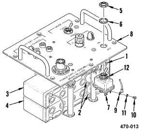
6. SWITCH S3 ASSEMBLY REPLACEMENT
REMOVAL
a. Remove control panel assembly (1 above).
b. Slide insulation sleeving (1) back on two
wires (2).
c. Tag and unsolder two wires (2) from
terminals of batteries BT1 (3) and BT2 (4).
d. Remove nut (5) and washer (6) from switch
S3 (7) and pull switch S3 (7) from control
panel (8).
e. Tag and unsolder five wires (9) from switch
S3 (7).