TM 1-1270-476-30
6-17
6-4. BRAKE RELEASE POWER SUPPLY ASSEMBLY REPAIR (cont)
3. RECHARGEABLE BATTERIES BT1 AND
BT2 REPLACEMENT
REMOVAL
a. Remove control panel assembly (1 above).
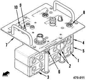
b. Slide insulation sleeving (1) back on two
wires (2) and jumper wire (3).
c. Tag and unsolder two wires (2) from
terminals of batteries BT1 (4) and BT2 (5).
d. Unsolder jumper wire (3) from terminals of
batteries BT1 (4) and BT2 (5).
NOTE
Note position of batteries BT1 and BT2 as
positive ends of batteries are opposite each
other.
e. Loosen four jamnuts (6) and slide batteries
from control panel assembly (7).
INSTALLATION
f. Insert batteries BT1 (4) and BT2 (5) into
control panel assembly (7) in proper
position. Tighten four jamnuts (6).
g. Solder two wires (2) to terminals of
batteries BT1 (4) and BT2 (5) and remove
tags.
h. Solder jumper wire (3) to terminals of
batteries BT1 (4) and BT2 (5).
i. Slide insulation sleeving (1) over terminals
of batteries.
j. Install control panel assembly (1 above).
k. Have installation inspected.
l. On the brake release power supply
assembly, set the power switch (8) to OFF.
NOTE
If test lamp illuminates, even if only dimly,
batteries are considered to be charged.
m. Press TEST switch (9). Observe TEST light
(10) is lit.
END OF TASK