TM 1-1270-476-30
6-25
6-5. BRANCHED CABLE ASSEMBLY W1 REPAIR (cont)
INSTALLATION
e. Install replacement contacts (para 2-5).
Refer to table 6 for connector wiring.
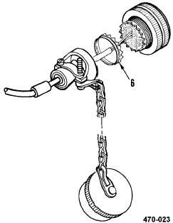
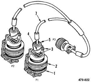
f. Slide seal ring (6), packing (5), and
backshell (4) down cable (7). Screw
backshell clockwise onto connector (2).
g. Tighten two screws (3) to close jaws of
backshell (4).
NOTE
If installing connector P3 contacts, disregard
step h.
h. Install cover (1) to connector P1 (2) by
turning in a clockwise direction.
i. Have installation inspected.
END OF TASK
Table 6. Connector Wiring
FROM
TO
Connector
Terminal
Connector
Terminal
P3
A
P1
48
P3
B
P1
50
P3
C
P2
L
P3
D
P2
g
P3
E
P1
49
P3
F
P2
f