TM 1-1270-476-30
6-20
6-4. BRAKE RELEASE POWER SUPPLY ASSEMBLY REPAIR (cont)
5. TOGGLE SWITCH S1 OR S2
REPLACEMENT
REMOVAL
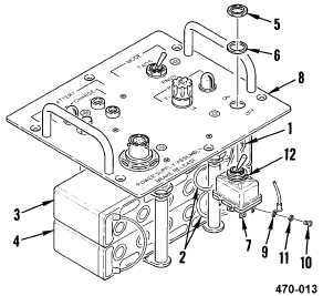
NOTE
This procedure is for replacing switch S1 or
S2. Switch S1 is shown.
a. Remove control panel assembly (1 above).
b. Slide insulation sleeving (1) back on two
wires (2).
c. Tag and unsolder two wires (2) from
terminals of batteries BT1 (3) and BT2 (4).
d. Remove nut (5) and washer (6) from switch
(7) and pull switch (7) from control panel
(8).
e. Tag and remove wires (9) from switch (7) by
removing screws (10) and washers (11).
INSTALLATION
f. Install wires (9) on switch (7) using screws
(10) and washers (11). Refer to table 2 or
table 3 for switch S1 or S2 wiring and
remove tags.
Table 2. Switch S1 Wiring
FROM
TO
S1-1
J2
S1-2
F1-1
S1-3
S2-2
S1-4
A1-E9
S1-5
F1-2
S1-6
A1-E11
BT1 (RED)
Table 3. Switch S2 Wiring
FROM
TO
S2-1
J1-C
S2-2
S1-3
DS2-1
S2-3
J1-A