TM 1-1270-476-30
6-19
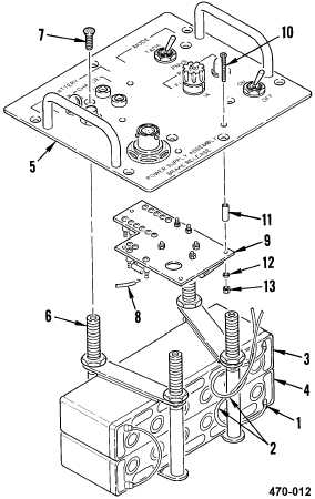
6-4. BRAKE RELEASE POWER SUPPLY ASSEMBLY REPAIR (cont)
INSTALLATION
g. Install electronic components assembly (9)
on control panel (5) using four screws (10),
spacers (11), washers (12), and locknuts
(13).
h. Solder nine wires (8) to electronic
components assembly (9), refer to table 1
for electronic components assembly wiring,
and remove tags.
i. Remove old corrosion inhibitive sealing and
coating compound from four screws (7)
(para 2-6).
j. Apply corrosion inhibitive sealing and
coating compound to four screws (7) (para
2-6).
k. Install control panel (5) on battery support
studs (6) using four screws (7).
l. Solder two wires (2) to terminals of
batteries BT1 (3) and BT2 (4) and remove
tags.
m. Slide insulation sleeving (1) over terminals
of batteries BT1 (3) and BT2 (4).
n. Have installation inspected.
o. Install control panel assembly (1 above).
END OF TASK
Table 1. Electronic Components
Assembly Wiring
FROM
TO
A1-E2
J3
BT2 (GRAY)
A1-E9
S1-4
A1-E10
S3-NC (1)
A1-E11
S1-6
DS1-1
A1-E14
S3-NO (1)
A1R1-1
DS2-2
A1R2-1
S3 NO (2)