TM 1-1270-476-30
6-23
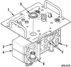
6-4. BRAKE RELEASE POWER SUPPLY ASSEMBLY REPAIR (cont)
7. CONNECTOR J1 CONTACT REPLACEMENT
REMOVAL
a. Remove control panel assembly (1 above).
b. Slide insulation sleeving (1) back on two
wires (2).
c. Tag and unsolder two wires (2) from
terminals of batteries BT1 (3) and BT2 (4).
d. Remove nut (5) from connector J1 (6) and
pull connector J1 (6) from control panel (7).
e. Remove contacts from connector J1 (6)
(para 2-5).
INSTALLATION
f. Install contacts in connector J1 (6) (para
2-5). Refer to table 5 for connector J1
wiring.
g. Position connector J1 (6) in control panel
(7). Install nut (5) on connector J1 (6).
h. Solder two wires (2) to terminals of
batteries BT1 (3) and BT2 (4) and remove
tags.
i. Slide insulating sleeving (1) over terminals
of batteries BT1 (3) and BT2 (4).
j. Have installation inspected.
k. Install control panel assembly (1 above).
END OF TASK
Table 5. Connector J1 Wiring
FROM
TO
J1-A
S2-3
J1-B
DS2-2
J1-C
S2-1
J1-D
J1-B