
TM 1-1500-204-23-11
(1) Facilities, Equipment and Materials. The
following equipment and materials are required: Vac-
uum Cleaner, HEPA Filter, Dual Action Sander or 90
degree die-grinder, 90 Degree Router Motor, 20,000
DO NOT sand into laminate near patch edge
RPM, Overhose Assembly, Sanding Disk Holder,
when sanding adhesive squeeze out.
Sanding Disks, 80 Grit, 1.0 Inch Diameter, Cutting
Wheel, Diamond Coated, 80 Grit, 1.0 Inch Diam-
(q) Repair the outer lightning mesh accord-
eter, Temperature/Vacuum Controller, Heat Blanket,
ing to paragraph 7-12 and the system
Adhesive Comb, Flash breaker Tape, Silicon Carbide
speciic technical manual if applicable.
Abrasive Paper, Wiping cloth, Release Film, Spat-
ula, Adhesive, Liquid (See System Speciic Technical
(r)
Reinish.
Manual), Fabric (See System Speciic Technical Man-
ual), Lightning Mesh (See System Speciic Technical
Sand the area smooth with 180 grit
1
Manual), Vacuum Bag Repair Materials Kit, Copper
abrasive paper. Vacuum the sand-
Sheet.
ing dust from the repair area. Wipe
with clean, dry cloth to remove
(2) Partial Thickness Scarf Repair
sanding residue.
Procedure.
Apply inish system in accordance
2
with paragraph 7-13b or the system
speciic technical manual.
DO NOT use oil or oil based materials
as NDI couplants on advanced composite
b. Partial Thickness Scarf Repair. Scarf repairs
components. Use only water or water based
are typically used to repair laminates on highly-loaded
materials. Disbonds may result and loss of
structures. The size of the repair area depends on
structural integrity may occur.
the thickness of the skin and the required scarf ratio.
Thicker structures require larger patches relative to the
(a) Remove dirt, grease and aircraft luids
original damage area. Highly-loaded structures require
from repair area as described in para-
high scarf ratios (e.g., 80 to 1), therefore, large-patch
areas in order to carry the necessary loads. As a
result, patch areas may be very large. Scarf ratios
(b) Deine both the depth and extent of the
are determined according to the loads that must be
damage using NDI according to para-
transferred. The scarf ratio for any repair in a given
graph 5-2 and the system speciic tech-
weapon system will be called out in the system speciic
nical manual. Lay out the damage as
technical manual or other authorizing document. Scarf
described in paragraph 6-4.
repairs can be used on all glass, carbon, and aramid
composite materials. Full thickness repairs generally
(c) Remove NDI couplant by wiping with
use scarf ratios of 20 to 1 while partial depth scarf
clean, water moistened cloth.
ratios are generally 30 to 1. Refer to igure 7-6 for
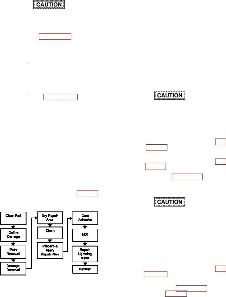
the Process Flow Diagram for Partial Thickness Scarf
Repair.
DO NOT sand into laminate when removing
paint. When working on a carbon iber lami-
nate, a black colored dust on the sandpaper
indicates that sanding into the laminate has
occurred and carbon iber is being removed.
If this occurs, the sanding process should
be stopped immediately. A loss of structural
integrity may occur if ibers are exposed or
damaged.
(d) Remove paint from skin in the repair
area by sanding as described in para-
(e) Remove partial thickness damage as
Figure 7-6. Process Flow Diagram for Partial
described in paragraph 6-4 and as
Thickness Scarf Repair
shown in igure 6-4. Use the scarf ratio