
TM 1-1500-204-23-11
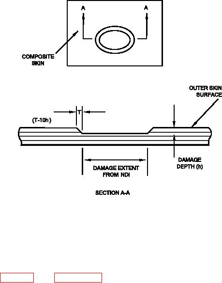
Figure 6-4. Partial Thickness Damage Removal
d. Core Damage. The most important considera-
the damage removal cutout is needed to minimize
tion in the removal of damaged core is maintaining
the gaps between the replacement core plug and the
a damage cutout that is parallel to the orientation of
core remaining in the part. Damaged core may be
the core cell axis. The cells of the core are nor-
removed by sanding, routing, cutting with a core knife
mally oriented 90 degrees to the centerline of the
or, in some instances, with a diamond-coated hole
repair part. See igure 6-5 and paragraph 7-5 for
saw.
cell core axis illustrations. The parallel orientation of