
TM 1-1500-204-23-11
Failure to properly cure adhesive in accor-
dance with the speciied cure cycle will result in
reduced repair strength may not be detectable
by visual or nondestructive inspection. This
may result in loss of structural integrity.
(9) Cure the adhesive with a heat lamp or heat
blanket according to paragraph 6-19, the
system speciic technical manual or the
resin manufacturer s speciications per engi-
neering disposition.
(10) Prepare the surface for coatings by sanding
the repaired area smooth with 240 grit abra-
sive paper being careful not to sand into the
laminate.
(11) Remove all dust by vacuuming or wiping with
a clean dry cloth.
(12) Paint according to paragraph 7-13b or the
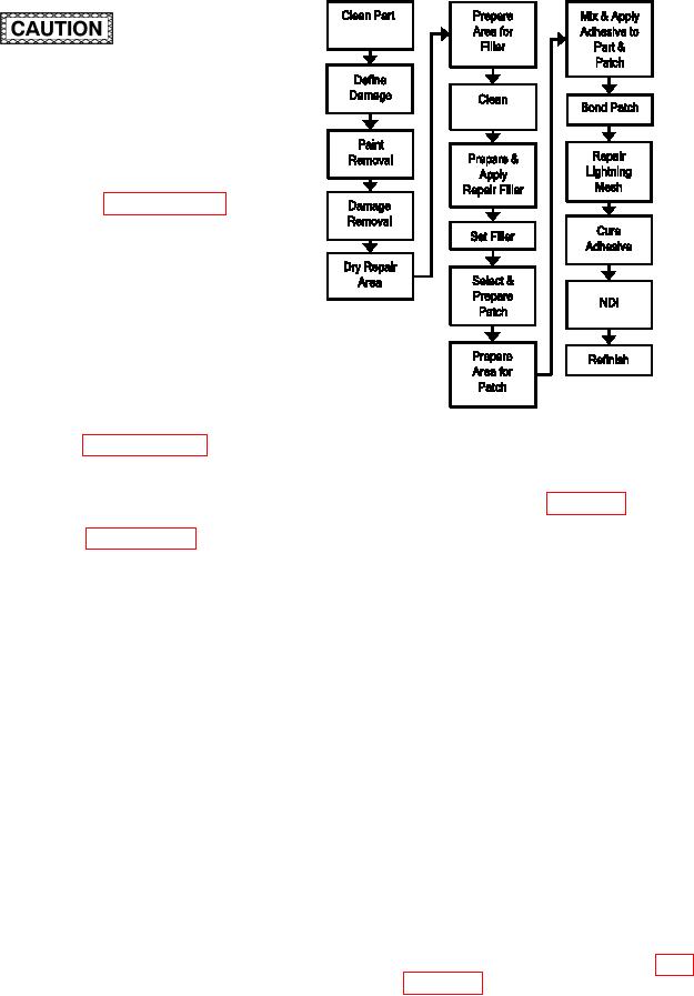
Figure 7-2. Process Flow Diagram For Partial
system speciic technical manual.
Thickness Damage
7-3. PARTIAL THICKNESS DAMAGE. This repair is
a. Bonded Repair. Refer to igure 7-2 for the
applicable to surface damage that exceeds the lim-
Process Flow Diagram for Partial Thickness Damage
its that can be repaired in paragraph 6-8 without
Bonded Repair.
penetrating the composite skin, and to the repair of
unsuccessful adhesive injection delamination repairs.
(1) Facilities, Equipment and Materials. The
This includes gouges, cracks and other damage that
following equipment and materials are required for
results in broken ibers. This repair procedure is not
repair: Vacuum Cleaner, HEPA Filter, Dual Action
necessarily applicable to a particular weapon system.
Sander or 90 degree die-grinder, 90 Degree Router
The applicability of this repair depends upon additional
Motor, 20,000 RPM , Overhose Assembly, Sanding
factors such as loading conditions and laminate thick-
Disk Holder, Sanding Disks, 80 Grit, 1.0 Inch Diam-
ness. Consult the system speciic technical manual
eter, Cutting Wheel, Diamond Coated, 80 Grit, 1.0
or engineering for further guidance.
Inch Diameter, Temperature/Vacuum Controller, Heat
Blanket, Adhesive Comb, Flash breaker Tape, Silicon
Carbide Abrasive Paper, Wiping Cloth, Release Film,
1 Mil, Spatula, Fiber (See System Speciic Techni-
cal Manual), Cut 0.1 Inch Long, Adhesive, Liquid
(See System Speciic Technical Manual), Adhesive,
Paste (See System Speciic Technical Manual), Light-
ning Mesh (See System Speciic Technical Manual),
Scrim Cloth, Vacuum Bag Repair Materials Kit, Copper
Sheet, Patch (See System Speciic Technical Manual).
(2) Bonded Repair Procedure.
(a) Remove dirt, grease and aircraft luids
from repair area as described in para-