
TM 1-1500-204-23-11
a. Full Thickness Scarf Repair. Full thickness
Technical Manual), Fabric (See System Speciic Tech-
scarf repairs are accomplished using the same pro-
nical Manual), Lightning Mesh (See System Speciic
cedures for a partial thickness repair per paragraph
Technical Manual), Vacuum Bag Repair Materials Kit,
7-3b with the exception that a taper ratio of 20
Copper Sheet.
to 1 is typical. Full thickness repairs may require
installation of a backside seal (see paragraph 6-18e).
(2) Full Thickness Scarf Repair Procedure.
Scarf repairs are typically used to repair laminates on
highly-loaded structures. The size of the repair area
(a) Remove dirt, grease and aircraft luids
depends on the thickness of the skin and the required
from repair area as described in para-
scarf ratio. Thicker structures require larger patches
relative to the original damage area. Highly-loaded
structures require high scarf ratios (e.g., 80 to 1),
therefore, large patch areas in order to carry the
necessary loads. As a result, patch areas may be
DO NOT use oil or oil based materials
very large. Scarf ratios are determined according to
as NDI couplants on advanced composite
the loads that must be transferred. The scarf ratio for
components. Use only water or water based
any repair in a given weapon system will be called
materials. Disbonds may result and loss of
out in the system speciic technical manual or other
structural integrity may occur.
authorizing document. Scarf repairs can be used on
all glass, carbon, and aramid composite materials.
(b) Deine both the depth and extent of the
Full thickness repairs generally use scarf ratios of 20
damage using NDI according to para-
to 1 while partial depth scarf ratios are generally 30 to
graph 5-2 and the system speciic tech-
1. This repair procedure is not necessarily applicable
nical manual. Lay out the damage as
to a particular weapon system. The applicability of
described in paragraph 6-4.
this repair depends upon additional factors such as
loading conditions and laminate thickness. Refer to
(c) Remove NDI couplant by wiping with
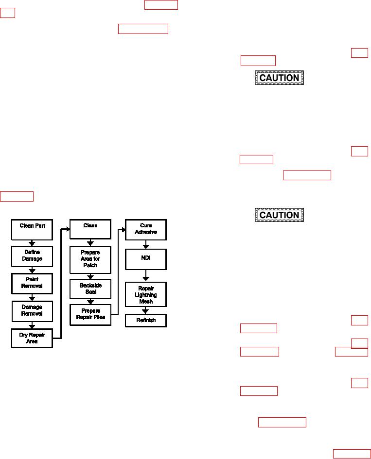
igure 7-7 for the Process Flow Diagram for Pene-
clean, water moistened cloth.
tration Damage Repair. Consult the system speciic
technical manual or engineering for further guidance.
DO NOT sand into laminate when removing
paint. When working on a carbon iber lami-
nate, a black colored dust on the sandpaper
indicates that sanding into the laminate has
occurred and carbon iber is being removed.
If this occurs, the sanding process should
be stopped immediately. A loss of structural
integrity may occur if ibers are exposed or
damaged.
(d) Remove paint from skin in the repair
area by sanding as described in para-
(e) Remove damage as described in para-
graph 6-15 and as shown in igure 6-4.
Use the scarf ratio from the system spe-
ciic technical manual.
Figure 7-7. Process Flow Diagram for Penetration
Damage Repair
(f)
Dry repair area as described in para-
graph 6-6 using a heat blanket to
(1) Facilities, Equipment and Materials. The
remove subsurface moisture.
following equipment and materials are required: Vac-
uum Cleaner, HEPA Filter, Dual Action Sander or
(g) Clean the repair area in accordance
90 degree die-grinder, Overhose Assembly, Sand-
with paragraph 6-7 in preparation for
ing Disk Holder, Sanding Disks, Temperature/Vacuum
replacement of the plies.
Controller, Heat Blanket, Flash Breaker Tape, Sili-
con Carbide Abrasive Paper, Wiping Cloth, Release
(h) Seal the backside of the damaged area,
Film, Spatula, Adhesive, Liquid (See System Speciic
if applicable, according to paragraph