
TM 1-1500-204-23-11
an approved solvent. Thoroughly clean the
area with repeated wiping until no residue is
left on the cloth.
(4) Measure the depth, length and width of the
surface damage to ensure compliance with
the limitations in the system speciic techni-
cal manual.
(5) Dry the repair area per paragraph 6-6 for a
minimum of 1 hour or as directed by the sys-
tem speciic technical manual, at 150 (+10)
F using a heat source per Chapter 3. Han-
dle the prepared surface of the part wear-
ing powder free latex gloves until after iller
application is complete. If iller is not to be
applied immediately, cover with clean barrier
material and secure with preservation tape
to prevent contamination.
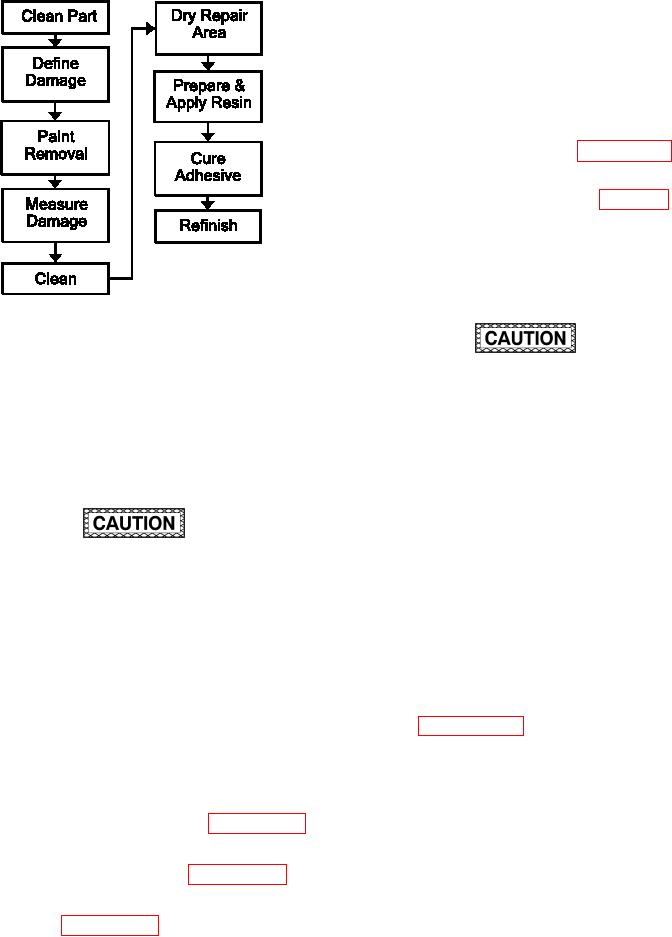
Figure 7-1. Process Flow Diagram for Surface
Damage
Reduced strength will result if the incorrect
a. Facilities, Equipment and Materials. These
mix ratio is used, if an excessive amount
include a vacuum cleaner, dual-action sander, and/or
of air is introduced into the adhesive during
90 degree die-grinder and sanding mandrel, lash
mixing, or if mixing is inadequate and may
breaker tape, silicon carbide abrasive paper, wiping
result in loss of structural integrity.
cloth, a spatula, adhesive liquid, and release ilm.
Pressure must be applied to adhesive within
b. Removal Procedures.
the pot life of the resin. For ambient temper-
atures in excess of 90 F, decrease this time
by 50%. An unsatisfactory repair will result
if the resin gels before adequate pressure is
applied and may result in loss of structural
DO NOT sand into laminate when removing
integrity. Select and prepare a heat blanket
paint. When working on a carbon iber lami-
(if required) and all necessary vacuum bag
nate, a black colored dust on the sandpaper
materials prior to mixing resin.
indicates that sanding into the laminate has
occurred and carbon iber is being removed.
(6) Prepare the adhesive by mixing a suitable
If this occurs, the sanding process should
resin and iber mixture following the system
be stopped immediately. A loss of structural
speciic technical manual. In the absence
integrity may occur if ibers are exposed or
of speciic instructions, use this mixing ratio:
damaged.
1.5 grams chopped iber to 48 grams resin.
Paragraph 6-17 describes resin mixing pro-
NOTE
cedures.
Fibrous mixtures are optional and need not
be used for scratches or dents.
(7) Fill the scratch or dent with the mixed resin
and iber mixture. Apply the adhesive in
(1) Remove dirt, grease and aircraft luids from
layered amounts to avoid air entrapment.
repair area as described in paragraph 6-5.
Bring lush with outer moldline surface of
part. Add additional iller as required to allow
(2) Remove paint from skin in the repair area by
for shrinkage.
sanding as described in paragraph 6-1.
(8) Place release ilm over repair. Smooth the
(3) Clean the scratch and/or dent in accordance
adhesive with a spatula and wipe off the
with paragraph 6-7 with wiping cloth and
excess with a clean, dry cloth.