
0121
TM 1-1740-221-13&P&P
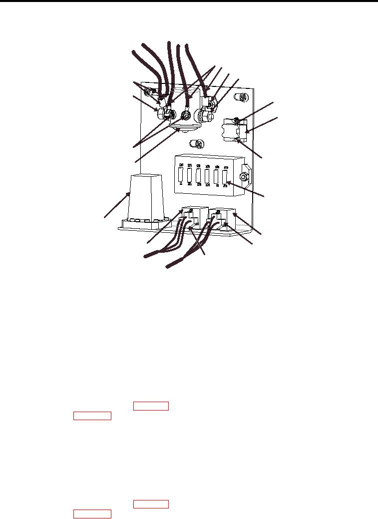
ELECTRIC PANEL (DASH) - (CONTINUED)
3
4
5
6
2
1
7
8
16
7
15
A
B
C
D
E
F
9
14
10
11
13
12
WP0101F1
Figure 1.
Electric Panel (Dash)
END OF TASK
REMOVAL
NOTE
Components in the electric panel are grouped together to ease maintenance.
Tag all wires during the removal process to aid in reinstallation.
ACCESSORY RELAY (CRA)
1. Disconnect battery negative cables (WP 0111).
2. Open dash panel (WP 0120).
3. Locate accessory (Figure 1, Item 15) relay referencing panel decal.
4. Remove nut and washer (Figure 1, Item 1) and remove 2 wires (Figure 1, Item 2).
5. Remove 2 nuts (Figure 1, Item 16) and remove 2 wires (Figure 1, Item 3).
6. Remove nut and washer (Figure 1, Item 6) and remove wire (Figure 1, Item 4).
7. Remove 2 relay mounting nuts and washers (Figure 1, Item 5) (one not shown).
8. Remove accessory relay (Figure 1, Item 15).
TIME DELAY RELAY (TRD)
1. Disconnect battery negative cables (WP 0111).
2. Open dash panel (WP 0120).
3. Locate accessory relay referencing panel schematic decal (Figure 1, Item 14).
01212