
TM 1-1740-221-13&P&P
FIELD MAINTENANCE
CREW PROTECTION SYSTEM (CPS) FAN
INITIAL SETUP:
Tools and Special Tools
References
Tool Kit, General Mechanic (WP 0157, Item 24)
Personnel Required
Light Wheel Vehicle Mechanic91B - 1
REMOVAL
1. Disconnect CPS wiring harness at steering plate (WP 0098, REMOVAL, Step 1).
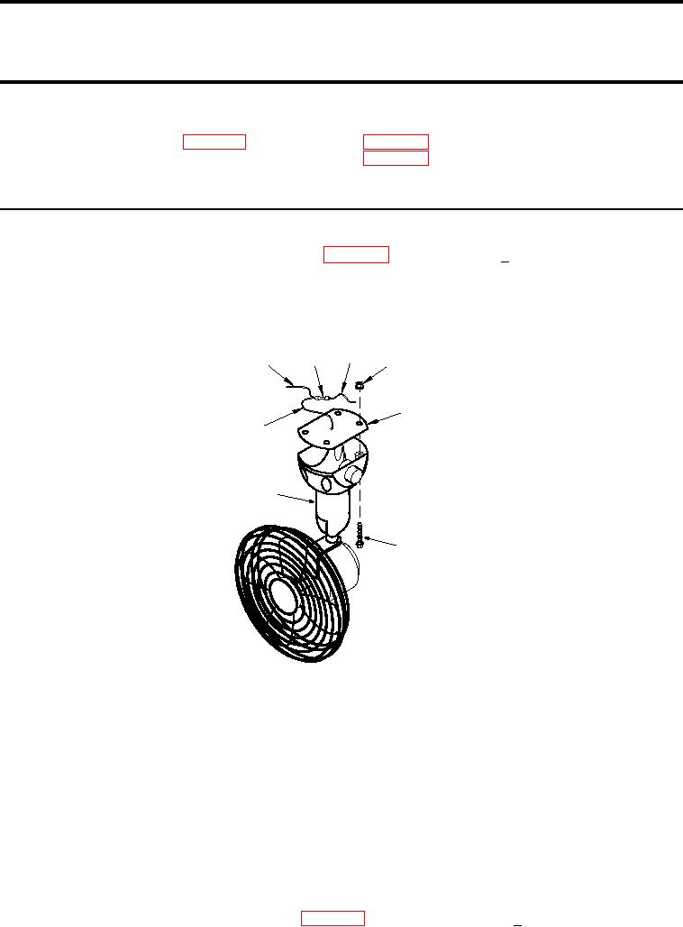
2. Cut CPS fan power supply wire (Figure 1, Item 8 ) on CPS fan side of splice at least 0.5 inch above splice
and cover exposed end of wire on splice side.
3. Remove four screws (Figure 1, Item 6) and four nuts (Figure 1, Item 4) securing CPS fan (Figure 1, Item
7) to cab and remove CPS fan and mount gasket (Figure 1, Item 5).
3
2
1
4
5
8
7
6
SATSCPScg0003
Figure 1.
CPS Fan
END OF TASK
INSTALLATION
1. Feed CPS fan power supply wire (Figure 1, Item 8) up through center hole in CPS cab mounting plate.
2. Install CPS fan (Figure 1, Item 7) and mount gasket (Figure 1, Item 5), with CPS fan switch facing the rear of
the CPS cab, to cab using four screws (Figure 1, Item 6) and four nuts (Figure 1, Item 4).
3. Remove splice (Figure 1, Item 2) between CPS dome light supply wire (Figure 1, Item 1) and fan/dome light
power supply wire (Figure 1, Item 3).
4. Splice CPS dome light power supply wire (Figure 1, Item 1) and CPS fan power supply wire (Figure 1, Item
8) to fan/dome light power supply wire (Figure 1, Item 3).
5. Connect CPS wiring harness at steering plate (WP 0098, INSTALLATION, Step 7).
01051