
0031
TM 1-1740-221-13&P&P
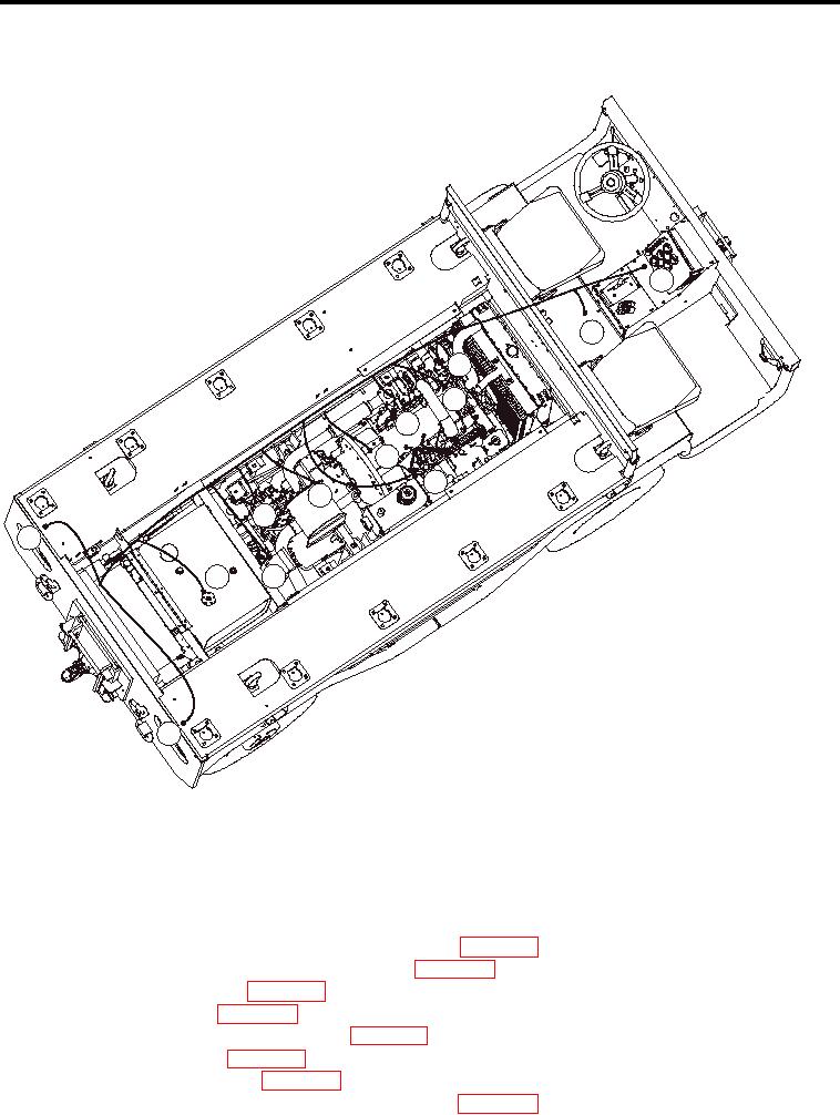
POWER PACK ASSEMBLY - (CONTINUED)
A
B
C
D
E
F
G
H
I
L
J
K
A-DASH PANEL
B-ELECTRIC PANEL BETWEEN SEATS
D-TEMPERATURE SENDER
E-STARTER
F-OIL PRESSURE SENDER
L
G-FUEL SHUT-OFF SOLENOID
H-TRANSMISSION TEMPERATURE SENDER
I-FUEL/WATER SEPERATOR
J-FUEL SENDER
K-STOPLIGHTS/BACK-UP LIGHTS
Figure 9.
Electric Wire Routing
20.
Route all engine pack wiring (Figure 9) as previously noted into vehicle.
21.
Connect engine block ground wire (Figure 3, Item 2) with nut (Figure 3, Item 1).
22.
Connect wire to engine coolant temperature sending unit (WP 0061).
23.
Connect wire to engine coolant temperature switch (WP 0060).
24.
Connect wiring to alternator (WP 0035).
25.
Connect wires to starter (WP 0034).
26.
Connect wires to throttle validation switch (WP 0125).
27.
Plug in fuel solenoid wire (WP 0066).
28.
Connect wire to glow plug rail (WP 0042).
29.
Connect wire to engine oil pressure (gauge) sending unit (WP 0038).
003111