
TM 1-1500-204-23-11
(d) Measure the panel thickness for deter-
mining the proper grommet length.
(e) Countersink OML side of cover as
described in paragraph 6-8 using a
countersink cutter and micro stop cage.
(f)
Spotface IML Surface.
Place a countersink cutter with the
1
same pilot diameter as the fastener
hole being repaired into a micro
stop cage. Center the countersink
pilot in the hole on the IML surface
of the cover.
With a marking pen or pencil, trace
2
around the perimeter of the micro
stop cage.
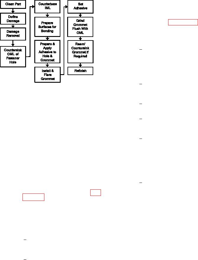
Figure 7-61. Process Flow Diagram for Fastener
Hole Repair: Swagged Grommet
Remove the countersink cutter
3
from the micro stop cage.
(1) Facilities, Equipment and Materials. The
following equipment and materials are required: Vac-
Remove pilot from the counterbore
4
uum Cleaner, HEPA Filter, Drill Motor, 2000 RPM,
cutter. Place counterbore cutter
Drill Guide, Alignment Pin, Dagger Drill Bits, Over-
into the micro stop cage.
hose Assembly, Marking Pen, 90 Degree Router Motor,
20,000 RPM, Sanding Disks, 80 Grit, 1.0 Inch Diame-
Center the micro stop cage over the
5
ter, Sanding Disk Holder, Microstop Cage, Countersink
hole with its perimeter aligned with
Cutter, Piloted, Counterbore Cutter, Removable Pilot,
the circle marked in step 2 above.
Grommet Installation Tool (Local Availability), Wiping
To stabilize the counterbore dur-
cloth, Solvent, Silicon Carbide Abrasive Paper, Cotton
ing cutting, place double sided tape
Tipped Applicator, Adhesive, Paste (See System Spe-
over the marked circle. Carefully
ciic Technical Manual), Double Sided Adhesive Tape,
place micro stop cage onto the tape
Pressure Sensitive, Grommet (Local Manufacture).
maintaining alignment.
(2) Swagged Grommet Repair Procedure.
Spotface IML side of cover to
6
a depth of 0.020 +0.005/-0.000
(a) Remove dirt, grease and aircraft luids
inches with counterbore cutter and
from repair area as described in para-
micro stop cage.
(g) Prepare surfaces for bonding. Clean
(b) Visually inspect and measure hole dam-
bonding surfaces of grommet and fas-
age. The damage must be no more than
tener hole using a cotton-tipped appli-
0.030 inch maximum on the radius.
cator, wiping cloth and solvent. Thor-
oughly clean the area with repeated
(c) Remove Damage.
wiping until no residue is left on the
cotton tipped applicator or the wiping
Locate original hole centerline
1
cloth. Handle the grommet and part
using the drill guide and alignment
from this point forward wearing powder
pin. Secure drill guide in place.
free latex gloves to prevent contamina-
tion of bonding surfaces.
While maintaining the original hole
2
centerline increase the hole diame-
ter 0.0625 inch using a dagger drill.