
TM 1-1500-204-23-11
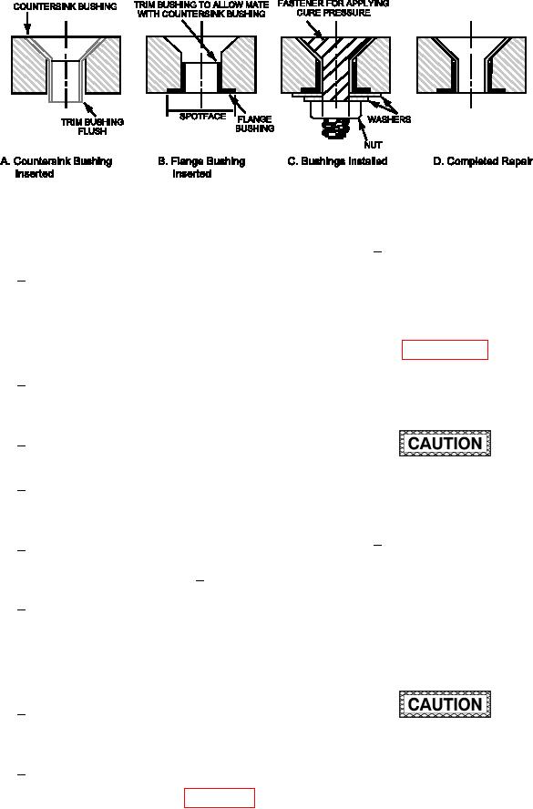
Figure 7-65. Captive Bushing Repair Flange and Countersink Bushing Installation
Clean bonding surfaces of bush-
(f)
Spotface IML Surface.
1
ings and fastener hole using a cot-
Place a countersink cutter with the
1
ton-tipped applicator, wiping cloth
same pilot diameter as the fastener
and solvent. Thoroughly clean the
hole being repaired into a micro
area with repeated wiping until no
stop cage. Center the countersink
residue is left on the cotton tipped
pilot in the hole on the IML surface
applicator or the wiping cloth. See
of the cover.
paragraph 6-7 for surface prepara-
tion steps. Handle bushings and
With a marking pen or pencil, trace
2
part from this point forward wearing
around the perimeter of the micro
powder free latex gloves to prevent
stop cage.
contamination of bonding surfaces.
Remove the countersink cutter
3
from the micro stop cage.
DO NOT allow release liquid to come into
Remove the pilot from the counter-
4
contact with repair of repair details. Disbonds
bore cutter. Place counterbore cut-
may result in loss of structural integrity.
ter into the micro stop cage.
Obtain a bolt, washer and nut
2
5
Center the micro stop cage over the
which will be used to clamp-up
hole with its perimeter aligned with
and retain bushings during cure.
the circle marked in step 2 above.
Coat the bolt, washer and nut with
liquid release agent. Apply a sec-
6
Spotface inner moldline side of
ond coat, waiting 15 minutes after
cover to a 0.020 +0.005/-0.000
each application to ensure solvent
depth with counterbore cutter and
in release agent completely evap-
micro stop cage.
orates. Cure per manufacturer s
instructions.
(g) Prepare Flange Bushing.
1
Determine length of lush bushing
to allow proper seating of counter-
sink bushing.
Reduced strength will result if the incorrect
mix ratio is used, if an excessive amount
Rough cut bushing to approximate
2
of air is introduced into the adhesive during
length using router motor and car-
mixing, or if mixing is inadequate and may
borundum wheel. See igure 7-65,
result in loss of structural integrity.
View B. Grind lange bushing to
Pressure must be applied to adhesive within
exact length using router motor and
the pot life of the resin. For ambient temper-
80 grit abrasive disk.
atures in excess of 90 F, decrease this time
(h) Prepare Surfaces for Bonding.
by 50%. An unsatisfactory repair will result