TM 1-1500-204-23-11
(j)
Leave grommet installation tool in place
and allow adhesive to set at room tem-
perature for 8 hours. Following removal
of installation tool, allow adhesive to set
at room temperature for an additional 16
hours before performing grinding oper-
ation.
(k) Grind excess grommet material lush
with OML surface using a router motor
and 80 grit abrasive disk. Use care not
to sand into laminate surface or over-
heat the laminate during grinding.
(l)
If required, ream and/or countersink
the grommet to comply with applicable
system speciic technical manual hole
diameter.
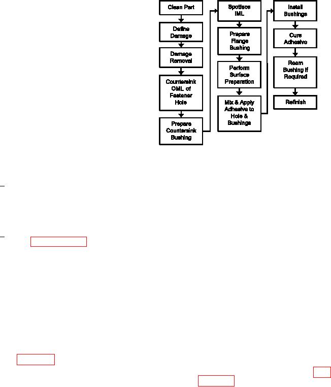
Figure 7-63. Process Flow Diagram Captive
(m) Reinish.
Bushing Repair
1
Sand the area smooth with 180
(1) Facilities, Equipment and Materials. The
grit abrasive paper. Vacuum the
following equipment and materials are required:
sanding dust from the repair area.
Piloted Reamer, Solid Carbide, 0.381 Inch Diameter,
Wipe with clean, dry wiping cloth to
Piloted Reamer, Solid Carbide, 0.4435 Inch Diameter,
remove sanding residue.
Vacuum Cleaner, HEPA Filter, Drill Guide, Drill Motor,
2000 RPM, 90 Degree Router Motor, 20,000 RPM,
Apply inish system in accordance
2
Overhose Assembly, Carborundum Wheel, Arbor, Drill
with paragraph 7-13b or the system
Chuck, Sanding Disk Holder, Sanding Disks, 80 Grit,
speciic technical manual.
1.0 Inch Diameter, Countersink Cutter, Piloted, Car-
bide Inserts, Countersink Cutter Pin, Microstop Cage,
h. Captive Bushing Repair. This repair is applica-
Counterbore Cutter, Removable Pilot, Bearing Press
ble to damaged or elongated fastener holes in struc-
(Common Support Equipment), Adhesive, Paste (See
tural composite panels such as removable access
System Speciic Technical Manual), Cotton Tipped
covers. This repair is limited to a maximum damage
Applicator, Solvent, Dry Ice (Local Availability), Flange
of 0.060 inch on the radius. Damage which exceeds
and Countersink Bushings 4 (1/4 Inch), Flange and
this limit requires engineering disposition. This repair
Countersink Bushings 5 (5/16 Inch), Spatula, Silicon
procedure is not necessarily applicable to a partic-
Carbide Abrasive Paper, Wiping cloth, and Release
ular weapon system. The applicability of this repair
Liquid.
depends upon additional factors such as loading con-
ditions and laminate thickness. Consult the system
(2) Captive Bushing Repair Procedure.
speciic technical manual or engineering for further
guidance. Refer to igure 7-63 for the Process Flow
(a) Remove dirt, grease and aircraft luids
Diagram for Captive Bushing Repair.
from repair area as described in para-
(b) Visually inspect and measure the hole
damage. The damage must be no more
than 0.060 inch maximum on the radius.
(c) Using a reamer, increase the hole diam-
eter by 0.131 inches. Ensure that the
original hole centerline is maintained.
(d) Countersink moldline side of cover or
panel to accept countersink bushing
using the appropriately sized counter-
sink cutter and micro stop cage.

