
TM 1-1500-204-23-11
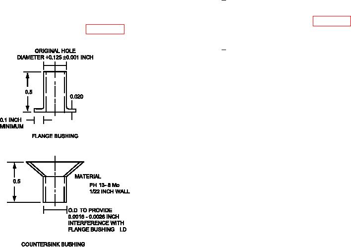
(e) Prepare Countersink Bushing. Two
1
Temporarily install countersink
lange and countersink bushings are
bushing and scribe outer diameter
listed. For other fasteners hole sizes,
of bushing lush with inner moldline
lange and countersink bushings may
surface of panel. See igure 7-65,
be fabricated per igure 7-64.
View A.
Remove bushing and rough cut
2
length to scribe line (lush with IML
surface) with router motor and car-
borundum wheel. Grind bushing
to exact length using router motor
and 80 grit abrasive disk.
Figure 7-64. Captive Bushing Repair Components