
TM 1-1500-204-23-11
(f)
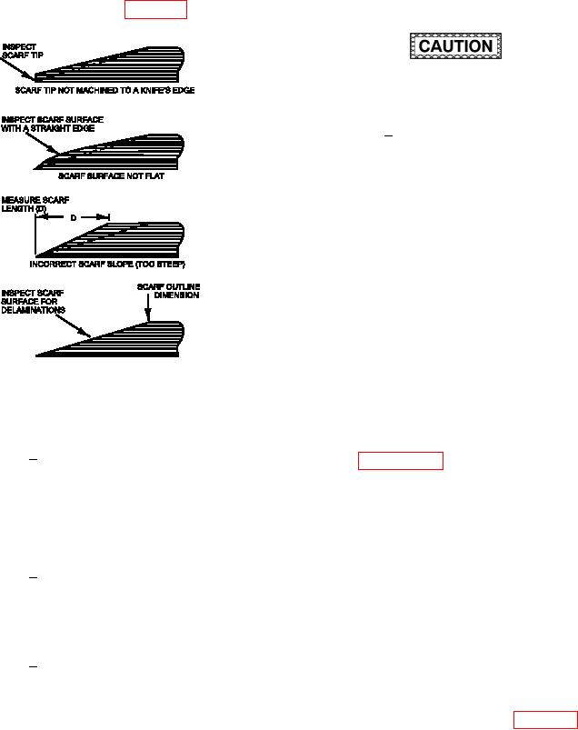
Inspect the inished scarf joint for the
scarf joint extends to the scarf out-
following: (See igure 6-23.)
line dimension marked in 6-15.g.
Do not scribe directly onto composite or metal.
Loss of structural integrity may occur.
The scarf joint tip must be
4
machined to a knife s edge to elim-
inate any stress concentrations at
the edge of the hole.
g. Step Joints. Generally, step joints are used in
ield repairs only on laminates made from woven
materials. This is because woven material, unlike
plies of unidirectional material, has a greater tendency
to separate between plies than within a ply. The
advantage to this is that the ply can be separated
along ply boundaries. This minimizes damage to
subsurface plies and ensures that the correct step
depth is achieved. Machining step joints on laminates
made from unidirectional pre-preg materials requires
the use of controlled depth router equipment and
templates. These are necessary to ensure that the
proper step depth and length is achieved. This repair
is dificult to perform on complex contours and is
better suited to depot level repairs.
Figure 6-23. Scarf Joint Inspection Requirements
(1) Outline and remove damage as described in
1
Visually inspect the scarfed sur-
paragraph 6-4b, Damage Removal.
face for the presence of preexisting
delaminations. Open up the dam-
(2) Determine the step outline perimeter.
age cleanup hole to remove all the
delaminated area (if present), and
(a) Determine the number of steps. The
redeine the perimeter of the scarf
number of steps is equal to the number
outline, as necessary.
of plies in the laminate minus one.
2
Inspect the scarf joint surface with
(b) Determine the step outline dimension
a straight edge. The scarf surface
(D) by multiplying the step length by the
must be lat and free of any convex
number of steps. In general, use a min-
or concave surfaces to avoid locally
imum step length of 0.5 inch. Refer to
changing the required slope.
the system speciic technical manual for
further guidance.
The required scarf joint slope must
3
be achieved. Too steep a slope
can result in premature joint failure.
(c) Measure outward from the damage
Too shallow a slope can remove an
cleanup hole edge the step outline
excessive amount of good mate-
dimension (D). (See igure 6-24). The
rial and/or move the joint into an
step outline perimeter is deined by this
area of higher loading. Ensure the
dimension