
TM 1-1500-204-23-11
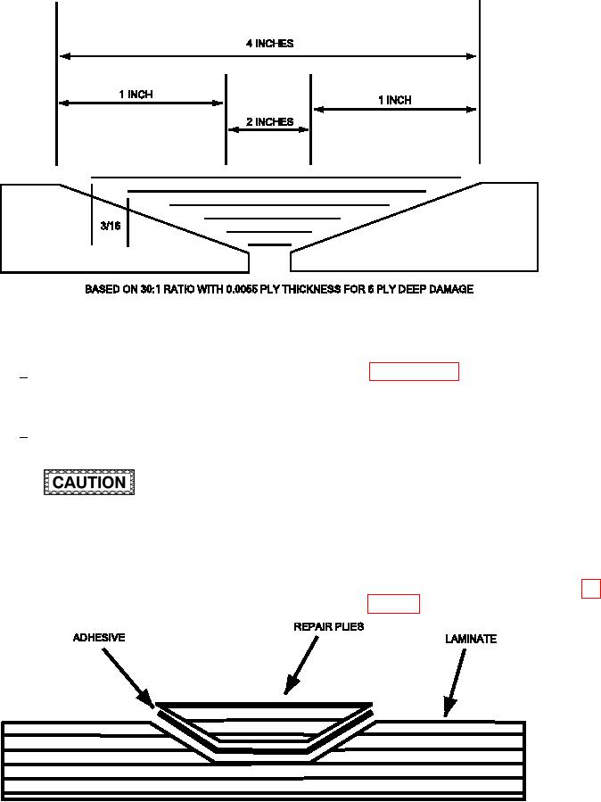
Figure 6-18. Dimensions of a Scarf Repair
Multiply the repair ply thickness by
paragraph 6-15f3(b)). Locate the cen-
4
the scarf ratio (0.0055 x 30 = 0.165
ter of the repair area and using an air-
inch).
craft marking pencil, mark perpendicu-
lar lines across the masking tape that
would extend through the repair center.
The overlap for this scarf repair
5
Orient the lines such that one of the lines
would be 0.165 inch per ply.
is parallel to a straight edge of the part.
Also, mark a circle on the part indicating
the minimum inished repair size.
(d) Determine the scarf outline perimeter.
Do not mark the composite with any method
that will indent or deform the surface.
(e) Measure the skin thickness (t). Multi-
ply the skin thickness by 20 to obtain
(c) Apply masking tape, centered on the
the scarf outline dimension (D). This will
repair area 1.0 inch beyond the mini-
provide a scarf slope of 20 to 1 (see ig-
mum inished repair size (determined in
Figure 6-19. Cross Section of Typical Scarf Repair