
TM 1-1500-204-23-11
(f)
Measure outward from the damage
sander such as a 3 inch dual-action
cleanup hole edge to the scarf outline
sander or a right angle die grinder may
dimension (D) (see igure 6-18). The
be used) the scarf into the laminate.
scarf outline perimeter is deined by
Ensure even concentric circles (indi-
this dimension. If variations in skin
cating different plies) and the correct
thickness are encountered, the scarf
ply overlaps are obtained. If the dam-
outline dimension (D) must be changed
age is all the way through the laminate,
accordingly.
the inner edge of the cutout can be
knife edged 0 to 0.005 inch. A ragged
appearance is acceptable.
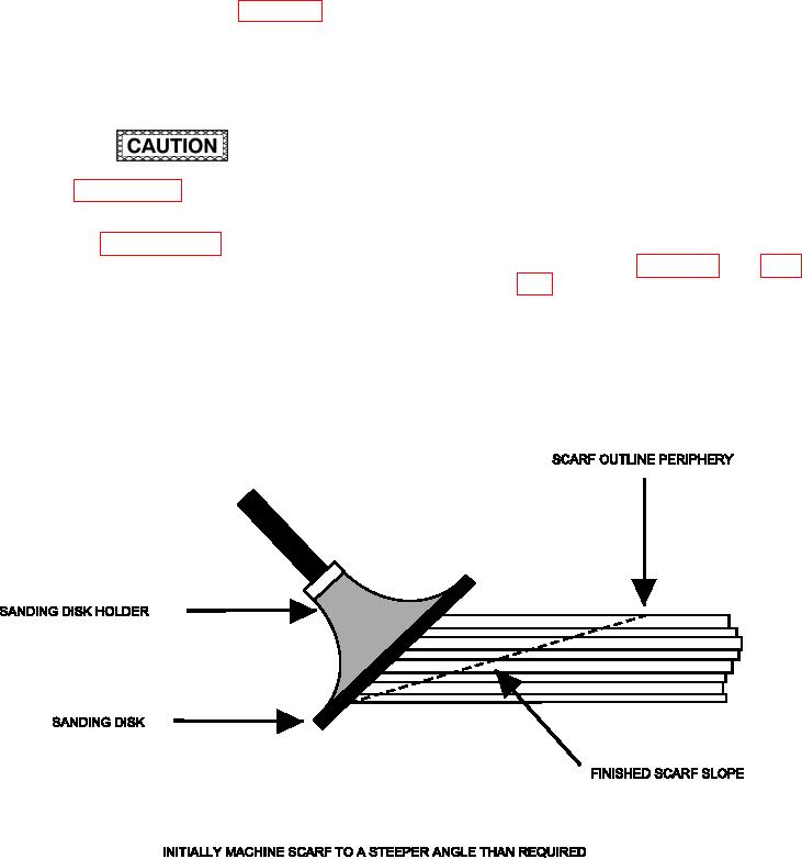
(b) Machine the edge of the damage
Refer to paragraph 6-8 or machining proce-
cleanup hole to a knife s edge using a
dures for composite materials. If a monolithic
90 degree router motor and an 80 grit
skin is being scarfed, seal the backside as
abrasive disk. Keep the knife s edge
described in paragraph 6-18.e prior to begin-
steeper than required for the inished
ning the scaring operation. This will prevent
scarf joint (see igure 6-20 and igure
the loss of ply material at the scarf tip during
6-21). This allows the skin plies to be
machining.
readily identiied and serves as a ref-
erence point for the remainder of the
(4) Scarf Joint Procedures. The following pro-
scaring operation.
cedures are used to determine scarf joint.
(a) Using 80 to 180 grit sandpaper, sand
by hand (or if properly skilled, a power
Figure 6-20. Scarf Joint Outline Layout