
TM 1-1500-204-23-11
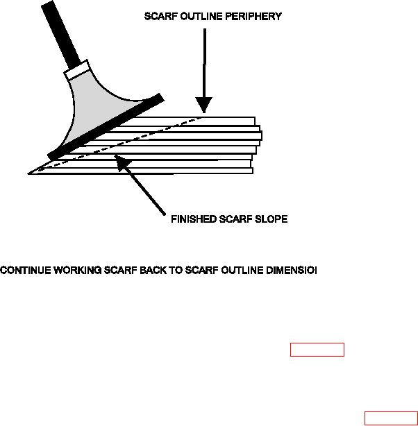
Figure 6-21. Scarf Joint Machining
(c) Using the powered sander, continue
(e) Record the orientation of each ply
working the scarf joint back to the scarf
removed with reference to a convenient
outline dimension determined to obtain
axis. See igure 5-12, Patch Drawing
the proper scarf slope. Sand carefully
Example. For most parts, this template
as the composite material is removed
provides a reference that will allow all
quickly. As the scarf outline dimension
plies to be oriented at 0, +45, and 90
is approached, use a sanding block and
degrees. Draw the coordinate axis
80 grit abrasive paper to inish the scarf
system on the part, outside the paint
joint.
removal line, as shown in igure 6-22.
Indicate the positive directions.
(d) Finish sanding the area inside the
masked area, including the border, with
150 to 180 grit abrasive (by hand or by
power sander).