TM 1-1270-476-30
4-174
4-12. DAY SENSOR SUBASSEMBLY REPAIR (cont)
i. Connect connector A19J1 (2) to connector
A19P1 and connector A19J2 (3) to
connector 1A5W1P14.
j. Install lacing and tying tape (1) to secure
connectors A19J1 (2) and A19J2 (3).
END OF TASK
4. TIME TOTALIZING METER ASSEMBLY
A18DS1 REPLACEMENT
NOTE
Time totalizing meter assembly A18DS1 is
being eliminated. If A18DS1 is located in the
day sensor subassembly, perform A18DS1
removal below. If A18DS1 is removed, do not
perform this procedure.
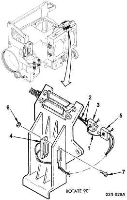
a. Cut lacing and tying tape (1) from
connectors.
b. Cut two wires (2) as close to P12 (3) as
possible.
c. Remove time totalizing meter assembly
A18DS1 (4) and connectors J1 (5) and P12
(3) by removing locknuts (6) and screws
(7).
d. Remove connector P12 (3) marker band
from cut wires.
e. Insulate cut wires (2) using insulation
sleeving. Ensure that tubing extends a
minimum of 0.25 inch beyond the cut ends.
f. Secure insulated wires (2) to adjacent
wiring or chassis using lacing and tying
tape.
g. Discard totalizing meter assembly A18DS1
(4), connectors J1 (5) and P12 (3), screws
(7), and locknuts (6) in accordance with TM
1-1270-476-23P.
END OF TASK