
TM 1-1730-223-13&P
FIELD MAINTENANCE
MAINTENANCE PLATFORM, ADJUSTABLE, MECHANICAL, AIRCRAFT
(B-1) PART NO. 1560-EG-100 NSN 1730-00-529-6235 EIC: UAT
ERECTING STRUT ASSEMBLY
INITIAL SETUP:
Equipment Condition
Remove handrails, platform rails, platform, rear legs
and steps. (WP 0015 00, Work Platform)
REMOVAL
HAND WHEEL
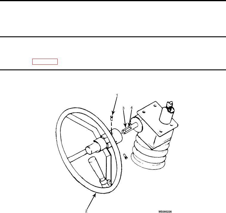
Figure 1.
Hand Wheel and Jack Screw.
1.
Loosen setscrews (Figure 1, Item 1).
2.
Pull hand wheel (Figure 1, Item 2) away from shaft (Figure 1, Item 3) and key (Figure 1, Item 4).
REPAIR OR REPLACEMENT
Straighten any bent areas. Weld cracks. Replace stripped setscrew. Re-tap stripped setscrew hole.
INSTALLATION
1.
Install hand wheel (Figure 1, Item 2) on shaft (Figure 1, Item 3) and key (Figure 1, Item 4).
2.
Tighten setscrews (Figure 1, Item 1).
0016 00-1