
TM 1-1730-223-13&P
0015 00
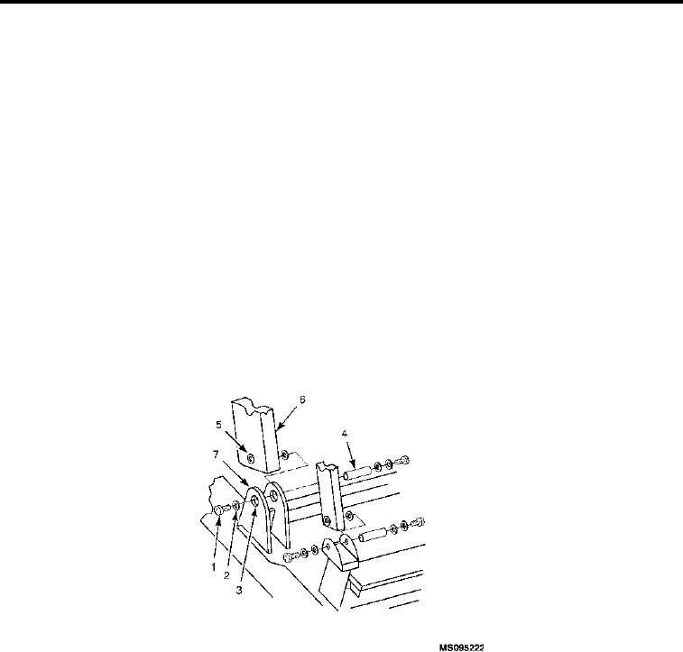
REMOVAL CONTINUED
STEPS
1.
Remove self-locking nut (Figure 5, Item 1), two flat washers (Figure 5, Item 2), and shoulder screw (Figure 5,
Item 3) attaching brace from step (Figure 5, Item 4) at each front leg (Figure 5, Item 5, View A).
2.
Remove self-locking nut (Figure 5, Item 6), two flat washers (Figure 5, Item 7 and 8), and shoulder screw
(Figure 5, Item 9) at each rear leg (Figure 5, Item 10, View B).
3.
Remove step (Figure 5, Item 4).
REPAIR OR REPLACEMENT
Straighten, weld and repaint steps as needed.
INSTALLATION
1.
Install step at rear leg (Figure 5, Item 10). Align holes.
2.
Secure with shoulder screw (Figure 5, Item 9), washers (Figure 5, Item 7 and 8) and self-locking nut (Figure
5, Item 6).
3.
Install step brace at front leg (Figure 5, Item 5) . Align holes.
4.
Secure with shoulder screw (Figure 5, Item 3) two flat washer (Figure 5, Item 2) and self-locking nut (Figure
5, Item 1).
REMOVAL
FRONT LEGS
Figure 6.
Front Legs.
1.
Remove handrails, platform rails, platform, rear legs and steps.
2.
Remove two cap screws (Figure 6, Item 1), two lock washers (Figure 6, Item 2), two flat washers (Figure 6,
Item 3), pivot pin (Figure 6, Item 4), and two lower washers (Figure 6, Item 5) from front leg (Figure 6, Item 6)
and main frame (Figure 6, Item 7).
3.
Remove front leg (Figure 6, Item 6) from bracket on main frame (Figure 6, Item 7).
REPAIR OR REPLACEMENT
Straighten, weld and repaint as needed.
INSTALLATION
1.
Reinstall rear leg (Figure 6, Item 6) in bracket on main frame (Figure 6, Item 7).
0015 00-7