
TM 1-1500-204-23-11
limited to a 4.0 inch diameter area. The blind fasteners
used in this repair must be designed for use on
composite materials. The rationale for these fasteners
is described in paragraph 3-4. This repair procedure
DO NOT use oil or oil based materials
is not necessarily applicable to a particular weapon
as NDI couplants on advanced composite
system. The applicability of this repair depends
components. Use only water or water based
upon additional factors such as loading conditions
materials. Disbonds may result and loss of
and laminate thickness. Consult the system speciic
structural integrity may occur.
technical manual or engineering for further guidance.
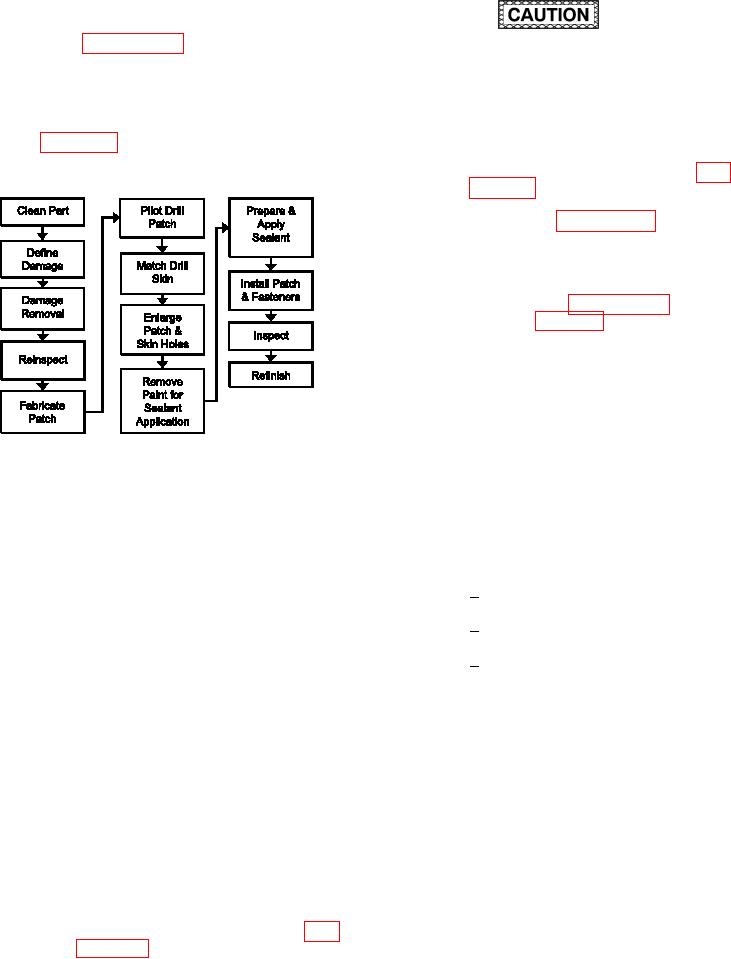
Refer to igure 7-30 for the Process Flow Diagram
(b) Deine both the depth and extent of the
for Partial Thickness Bolted Repair.
damage using NDI according to para-
graph 5-2 and the system speciic tech-
nical manual. Lay out the damage as
described in paragraph 6-4. Mark cen-
terlines to be used as reference marks
for positioning patch.
(c) Remove partial thickness damage as
described in paragraph 6-4 and as
shown in igure 6-4.
(d) Reinspect the damage removal area
using NDI to ensure no skin delamina-
tions remain below the damage area.
(e) Remove NDI couplant by wiping with
clean, water moistened cloth.
Figure 7-30. Process Flow Diagram for Partial
(f)
Fabricate metallic patch as described
Thickness Bolted Repair
in TM 1-1500-204-23-10 or the system
speciic technical manual. Refer to the
(1) Facilities, Equipment and Materials. The
system speciic technical manual for
following equipment and materials are required: Drill
speciic patch geometry/material, and
motor, Drill guide, Drill bits, high-speed steel, Drill
fastener hole pattern layout.
reamer, carbide, straight lute, Center punch, Tempo-
rary fasteners, Approved marker, Grip Length Gauge,
Lay out patch on required material.
1
Vacuum Cleaner, HEPA Filter, Composite Fasten-
ers Installation Tooling, Patch material (See System
Cut out patch and chamfer edges.
2
Speciic Technical Manual), Silicon Carbide Abrasive
Paper, Wiping cloth, Composite Blind Fastener (see
Form contour in patch if required.
3
System Speciic Technical Manual).
(g) Lay out pilot hole pattern on patch.
(2) Partial Thickness Bolted Repair
Procedure.
(h) Position patch over damaged area,
using reference marks on skin as a
NOTE
guide. Outline patch perimeter on skin
and transfer reference marks from skin
The following procedure assumes the sys-
to patch.
tem speciic technical manual or engineering
has provided a fastener layout based upon
(i)
Remove patch. Identify any skin fasten-
the repair design and/or criteria. Use an
ers covered by the repair patch.
approved drill guide for all drilling operations.
Consult the system speciic technical manual
for guidance.
(a) Remove dirt, grease and aircraft luids
from repair area as described in para-