TM 1-1500-204-23-11
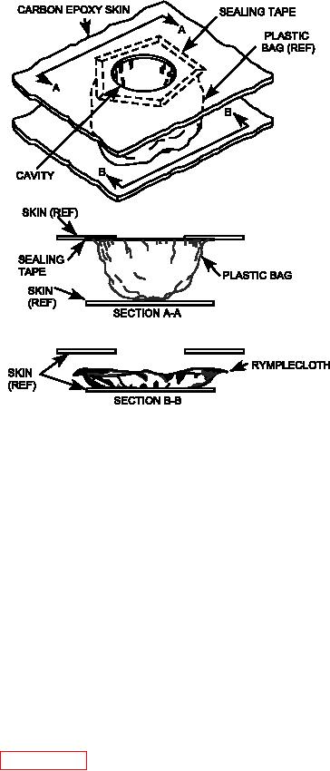
Figure 7-28. Sump Removal and Installation
(g) Lay out pilot hole pattern on patch.
(m) Using a 2000-rpm drill motor, drill guide,
and a No. 30 HSS drill bit and back-
ing plate, drill all the holes. Deburr the
(h) Position patch over damaged area,
holes.
using reference marks on skin as a
guide. Outline patch perimeter on skin
and transfer reference marks from skin
(n) On the drilled patch, mark one piloted
to patch.
hole in each of the patch corners. These
holes will be used as alignment holes for
aligning and match drilling the patch to
(i)
Remove patch. Identify any skin fasten-
the structure.
ers covered by the repair patch.
(o) Place the patch onto the repair area in
(j)
On the drilled patch, mark one piloted
its proper location and orientation and
hole in each of the patch corners. These
mark the irst hole to be drilled.
holes will be used as alignment holes for
aligning and match drilling the patch to
the structure.
(p) Remove patch and check to ensure fas-
tener hole to edge of damage cleanup
meets the minimum requirement in the
(k) If applicable, remove any existing fas-
system speciic technical manual. If any
teners covered by the repair plate as
fastener hole has less than the required
described in paragraph 4-5d. Transfer
edge distance, repeat step (k) above,
the fastener hole locations to the repair
relocating patch to obtain required edge
patch using the methods described in
distance.
paragraph e above.
(l)
Using a center punch, mark the loca-
(q) Using a 2000 rpm drill motor, drill guide,
tions on the metal patch that require
a straight-luted carbide drill reamer,
pilot holes.
and the patch holes as the template or

