TM 1-1500-204-23-11
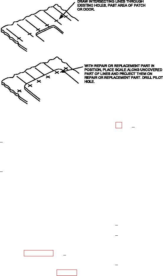
Figure 7-24. Measuring and Scaling Method of Transferring Blind Holes
7-7e3(a)1 was used, mark the fastener
(a) Using a marking pen or pencil, complete
hole locations on the replacement part
one of the following:
by transferring the measured distance
onto the projected lines.
Draw a line through the center of
1
each existing fastener hole in the
structure. Mark off a measured dis-
(e) If any pilot or full size holes exist in the
tance on each line from the center
replacement part, inspect and compare
of each existing hole.
the alignment of each hole location in
the new part to the holes in the original
structure. If only pilot holes exist in the
At each fastener hole, draw two
2
new part, adjust the part so as many of
lines intersecting at the hole center.
the pilot holes as possible are located
in the center of the existing holes in the
(b) Position and align the new part on the
structure. If adjusted, repeat the para-
structure.
graph above to ensure all hole center-
lines are properly located.
(c) Install temporary fasteners in any full
size fastener holes in the replacement
(f)
If the new part has previously drilled
part to secure the part in position. If
pilot holes, complete the following:
no full size fastener holes exist in the
replacement part, tape the part in posi-
Remove the part from the structure.
1
tion.
Enlarge the pilot holes to full size.
2
(d) Place a straight edge along each of the
Use several intermediate size drills
uncovered lines previously marked and
to bring holes to inal size. Be care-
transfer these lines onto the replace-
ful to keep drills centered on the
ment part. If the two intersecting lines
fastener holes.
method in paragraph 7-7e3(a)2 was
used, the fastener locations on the
replacement part are at the intersect-
Reinstall part with temporary fas-
3
ing lines on the replacement part. If
teners.
the measuring method in paragraph

