
TM 1-1500-204-23-11
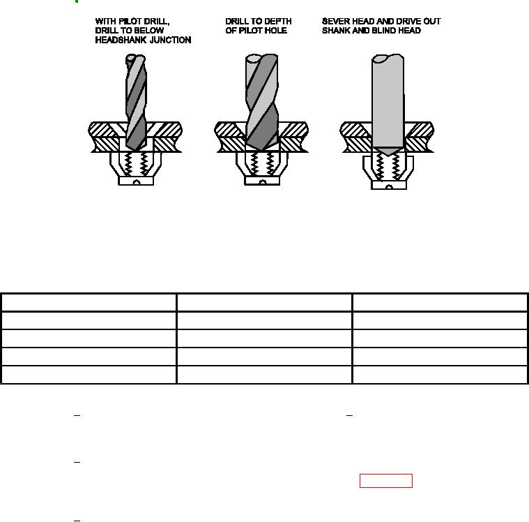
Figure 7-20. Removal of Tightly Clamped Blind Fasteners
Pilot and Shank Drill Sizes for Blind Fastener Removal
FASTENER DIAMETER
PILOT DRILL SIZE
SHANK DRILL SIZE
0.1635
0.0980 (No. 40)
0.1540 (No. 23)
0.1980
0.1285 (No. 30)
0.1890 (No. 12)
0.2590
0.1590 (No. 21)
0.2460 (D)
0.3105
0.1730 (No. 17)
0.2950 (M)
3
With a round carbide burr, grind an
6
With a hammer and minimal size
indentation in the center of the fas-
punch, sever the head and drive
teners to be removed.
out the shank and blind head.
Using the pilot drill and a drill guide,
4
(b) Perform the following steps to remove
drill on the centerline of the fastener
fasteners that turn when drilling. Refer
to be removed. Drill to below the
to igure 7-21.
head-to-shank juncture.
Using the shank drill and drill guide,
5
drill in each fastener hole to the
depth of the pilot hole.