TM 1-1270-476-30
4-324
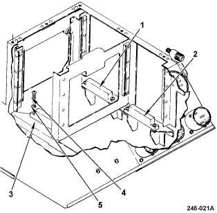
4-38. HARNESS ASSEMBLY REPAIR (cont)
4. CONNECTOR XA13, XA14, OR XA15
REPLACEMENT
NOTE
This procedure is for replacing connector
XA15 (3) and can also be used for replacing
connector XA13 (1) or XA14 (2).
REMOVAL
a. Remove top assembly cover (para 4-37).
NOTE
To gain access to connectors XA13, XA14, or
XA15, the applicable CCA must be removed.
To replace connector
Remove CCA
XA13 (1)
A13
XA14 (2)
A14
XA15 (3)
A15
b. Remove applicable CCA (para 4-37).
c. Remove faulty connector from chassis
assembly by removing two screws (4) and
washers (5).
d. Remove faulty connector from wiring
harness (para 2-5).
INSTALLATION
e. Install connector on wiring harness (para
2-5).
f. Install connector in chassis assembly using
two screws (4) and washers (5).
g. Install applicable CCA A13, A14, or A15
(para 4-37).
END OF TASK