TM 1-1270-476-30
4-319
4-38. HARNESS ASSEMBLY REPAIR
This task covers replacement of:
Para
Item
1.
Connector J1, J3, or J4 contact
2.
Connector A1P1 or A1P2
3.
Connector XA10 or XA11
4.
Connector XA13, XA14, or XA15
5.
Connector P3
Para
Item
6.
Connector J5
7.
Connector J6
8.
Connector P8
9.
Elapsed time indicator ETI
INITIAL SETUP
Tools
Aircraft armament repairman tool set
Aircraft armament technical inspector tool set
Materials (appendix C)
Heat shrinkable insulation sleeving (Item 28)
Heat shrinkable insulation sleeving (Item 31)
Lacing and tying tape (Item 56)
Personnel Required
68J Aircraft Fire Control Repairer
66J30 Aircraft Armament Technical Inspector
CAUTION
While performing this procedure keep all
exposed lens covered with lens paper to
prevent damage to coated optical surfaces.
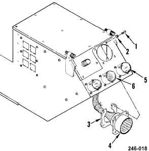
1. CONNECTOR J1, J3, OR J4 CONTACT
REPLACEMENT
NOTE
This procedure is for repairing connector J1 (4)
and can also be used for repairing connector
J3 (5) or J4 (6).
REMOVAL
a. Remove rear assembly cover (para 4-37).
b. Remove faulty connector by removing four
screws (1), washers (2), and connector
plate (3).
c. Remove faulty contact from connector
(para 2-5).


