TM 1-1270-476-30
4-322
4-38. HARNESS ASSEMBLY REPAIR (cont)
3. CONNECTOR XA10 OR XA11
REPLACEMENT
NOTE
This procedure can be used to replace
connector XA10 or XA11.
REMOVAL
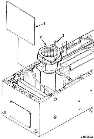
a. Remove bottom assembly cover (para
4-37).
b. Remove CCA A5 (1) using card extractor.
c. Remove fan assembly (2) by removing four
screws (3) and lifting from housing.
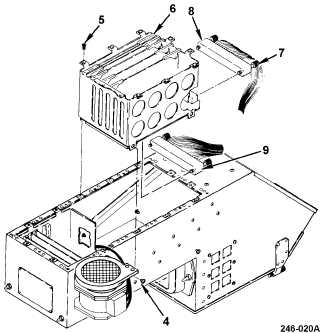
d. Loosen four captive screws (4).
e. Remove eight screws (5) and remove CCA
cage (6).
f. Disconnect faulty connector by loosening
two screwlocks (7).
Connector XA10 (8)
Connector XA11 (9)
g. Remove faulty connector from wiring
harness (para 2-5).