TM 1-1270-476-30
4-231
4-29. CONTROL PANEL ASSEMBLY 2A1 REPAIR (cont)
2. ILLUMINATED PANEL ASSEMBLY A1 OR
A2 REPLACEMENT
REMOVAL
a. Remove HOD assembly (1 above).
NOTE
Illuminated panel assembly A1 and A2 wires
are black.
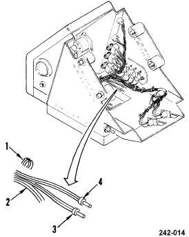
b. Cut lacing and tying tape (1) securing
illuminated panel lead wires (2) to wiring
bundle.
c. Pull panel lead wires (2) until splices (3)
and (4) are away from control panel
housing and tag wires.
d. Cut both splices (3) and (4) from wires (2).
Discard splices.
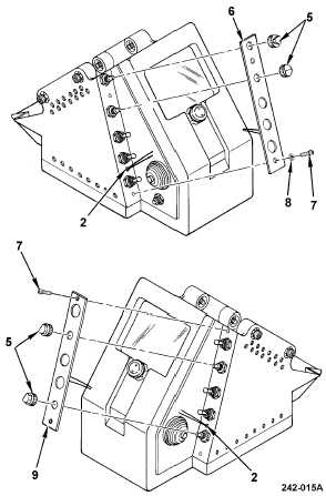
e. Remove knob assemblies (5) by loosening
setscrews securing knobs to control shafts.
f. Remove faulty illuminated panel A1 (6) by
removing two screws (7) and washers (8)
or remove faulty illuminated panel A2 (9) by
removing two screws (7). Lift panel until
lead wires clear control panel housing.
INSTALLATION
g. Feed panel lead wires (2) through hole in
control panel housing, then pull wires (2)
through housing.
h. Install illuminated panel A1 (6) and secure
with two screws (7) and washers (8) or
install illuminated panel A2 (9) and secure
with two screws (7).
i.
Install knob assemblies (5) on control
shafts and tighten setscrews.