TM 1-1270-476-30
4-228
4-29. CONTROL PANEL ASSEMBLY 2A1 REPAIR
This task covers replacement of:
Para
Item
1.
Heads out display (HOD) assembly
2.
Illuminated panel assembly A1 or A2
3.
Resistor R1, R2
4.
Switch S1, S2, or S11
5.
Resistor R4 or R5
6.
Switch S3, S4, or S5
7.
Switch S6
8.
Switch S7 or S8
Para
Item
9.
Switch S9 or S10
10.
Resistor R6 or R3
11.
Resistor R7, R8, R9, or R10
12.
Resistor R3 adjustment
13.
Resistor R6 adjustment
14.
Shock pad
15.
Connector J3 contacts
16.
Terminal lug E1
17.
Night filter assembly
INITIAL SETUP
Tools and Special Tools
Aircraft armament repairman tool set
Aircraft armament technical inspector tool set
Rubber apron
Rubber gloves
Acid-type goggles
Materials (appendix C)
Abrasive paper (Item 43)
Adhesive sealing compound (Item 76 or 77)
Chemical film (Item 9)
Corrosion inhibitive sealing and coating
compound (Item 15 or 16)
Cotton, lint-free cloth (Item 8)
Hot air shrinkable conductor splice (Item 49)
Lacing and tying tape (Item 56)
Masking tape (Item 59)
Solder (Item 48)
Trichloroethane (Item 62)
Personnel Required
68J Aircraft Armament Repairer
66J30 Aircraft Armament Technical Inspector
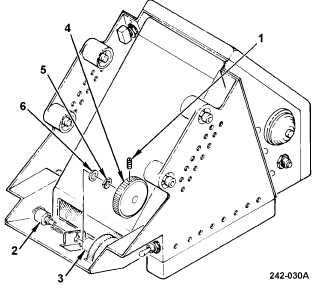
1. HEADS OUT DISPLAY (HOD) ASSEMBLY
REPLACEMENT
REMOVAL
a. Loosen two setscrews (1) on resistor R3 (2)
and R6 (3) thumbwheels (4) and slide
thumbwheels away from resistors as far as
possible.
b. Loosen R3 and R6 mounting nuts (5)
enough to pull thumbwheels clear of
resistor shafts. Remove thumbwheels and
set aside. Remove nuts (5) and
lockwashers (6) and set aside. Reseat R3
(2) and R6 (3) in mounting brackets.