
TM 1-1740-221-13&P&P
FIELD MAINTENANCE
DIRECTIONAL SIGNAL ARM
INITIAL SETUP:
Tools and Special Tools
References
General Mechanics Tool Kit (WP 0157, Item 24)
Materials/Parts
Wire Ties (WP 0156, Item 47)
Personnel Required
91B, Light Wheel Vehicle Mechanic
INSPECTION
Inspect directional signal arm assembly for mounting security, excessive wear, proper electrical connections and
damage affecting serviceability.
END OF TASK
REMOVAL
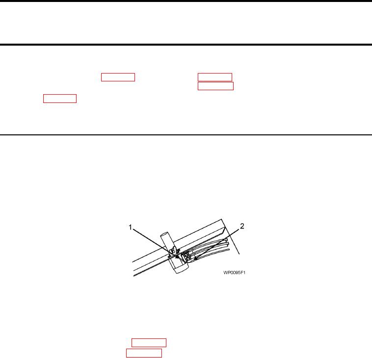
Figure 1. Horn Wire and Wire Harness
NOTE
Note orientation of wire harness connectors and wire ties to aid in reinstallation.
1.
Disconnect battery negative cables (WP 0111).
2.
Remove orbital valve cover panel (WP 0136).
3.
Disconnect horn wire (Figure 1, Item 1).
4.
Disconnect remaining 5 wiring harness connectors (Figure 1, Item 2) from under the center console area
under the vehicle.
5.
Carefully pull wiring harness (Figure 1, Item 2) from center console area.
6.
Remove mount clamp (Figure 3, Item 1).
7.
Remove directional signal arm assembly.
END OF TASK
01151