0112
TM 1-1740-221-13&P&P
HARNESS - (CONTINUED)
2
1
3
WP0092F1
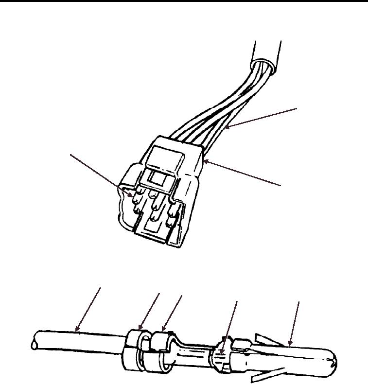
Figure 1.
Connector Removal.
1
2
3
4
5
WP0092F2
Figure 2. Connector Installation.
Sealed Connector Replacement
1. Open hinged cover (Figure 3, Item 8) of connector (Figure 3, Item 7) for access to rear of connector.
NOTE
Perform the following steps for each wire of connector.
2.
Tag wires to aid in installation.
3.
Using pin removal tool, position tool over pin (Figure 3, Item 6) and push inward to retract two barbs of pin.
01122

