
0112
TM 1-1740-221-13&P&P
HARNESS - (CONTINUED)
4.
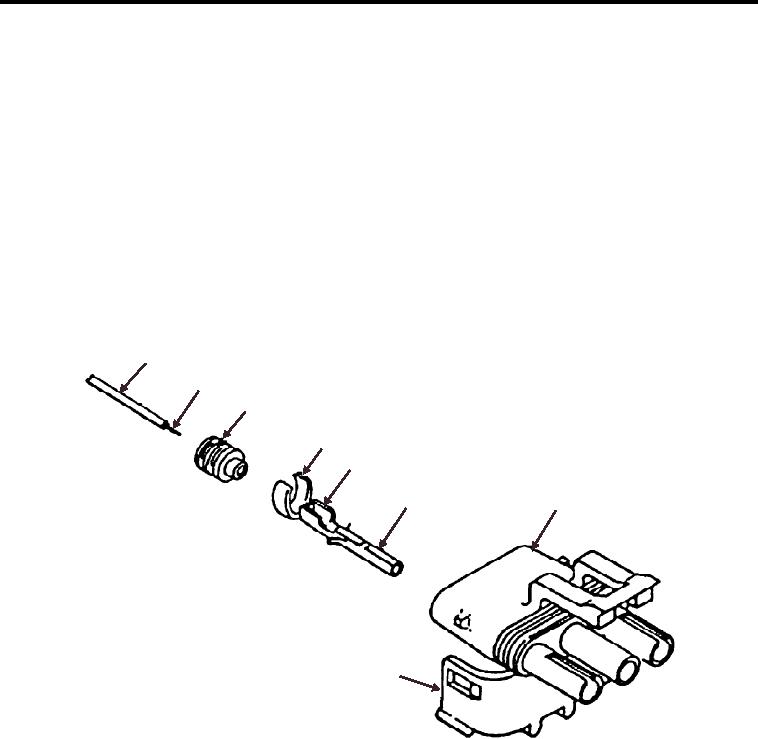
Remove wire (Figure 3, Item 1) with pin (Figure 3, Item 6) and seal (Figure 3, Item 3) attached, from rear of
connector (Figure 3, Item 7).
5. If defective, remove pin (Figure 3, Item 6) and seal (Figure 3, Item 3) from wire (Figure 3, Item 1) by cutting
through wire just behind seal.
6. Position new seal (Figure 3, Item 3) on wire (Figure 3, Item 1).
7. Using wire stripping tool, strip insulation of wire (Figure 3, Item 1) to expose 1/8 in. (3 mm) length of metal
strands (Figure 3, Item 2).
8. Using crimping tool, securely crimp tabs (Figure 3, Item 5) of pin (Figure 3, Item 6) over metal strands
(Figure 3, Item 2) of wire (Figure 3, Item 1).
9. Slide seal (Figure 3, Item 3) next to pin (Figure 3, Item 6) and crimp tabs (Figure 3, Item 4) of pin over
end of seal.
10. Push pin (Figure 3, Item 6) into rear of connector (Figure 3, Item 7) until fully seated. Remove tags.
11. Close hinged cover (Figure 3, Item 8) of connector (Figure 3, Item 7).
1
2
3
4
5
6
7
8
WP0092F3
Figure 3. Sealed Connector Replacement.
01123