
TM 1-1740-221-13&P&P
FIELD MAINTENANCE
HAND BRAKE LEVER
INITIAL SETUP:
References
Tools and Special Tools
General Mechanic Tool Box (WP 0157, Item 24)
Wheel Chock Blocks (WP 0155, Item 25)
Equipment Condition
Personnel Required
Engine Shut Down
91B, Light Wheel Vehicle Mechanic
INSPECTION
Visually inspect hand brake lever for corrosion, bent or broken parts and security of mounting. Ensure lever and
adjustment knob is properly lubricated and operates smoothly.
3
4
2
1
5
WP0079F1
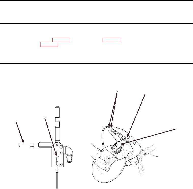
Figure 1. Hand Brake Cable Adjustment
END OF TASK
ADJUSTMENT
1. Release hand brake lever.
2. Turn handle grip (Figure 1, Item 1) counter clockwise to center pin (Figure 1, Item 2) in slot.
3. Release the two locknuts at (Figure 1, Item 3) and adjust the cable length to give 0.40 - 0.60 in. (10 - 15
mm) of caliper lever movement at the outer cable hole (Figure 1, Item 4). The total clearance between the
brake pad and brake disc should be 0.02 - 0.03 in. (0.50 - 0.75 mm).
4. Make sure there is adequate movement of caliper lever (Figure 1, Item 5) to ensure a positive brake
application and that caliper lever returns to the rest position when hand brake is released.
5. Test hand brake. Make inal adjustments as required at hand brake lever.
END OF TASK
00881