
0086
TM 1-1740-221-13&P&P
PARK POSITION BRAKE LIMIT SWITCHES - (CONTINUED)
1
2
7
3
4
5
2
4
1
6
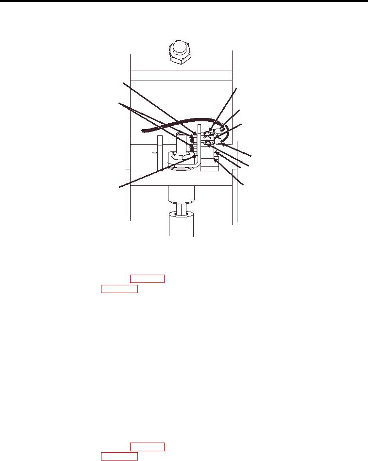
WP0077F2
Figure 2. Upper Limit Switch Guard
LOWER LIMIT SWITCH
1. Disconnect battery negative cables (WP 0111).
2. Remove center deck plate (WP 0028).
3. Loosen spring arm mount bolt (Figure 3, Item 1).
NOTE
Note position of spring arm assembly (9 o'clock).
4.
Remove spring arm assembly (Figure 3, Item 11) from switch shaft.
5.
Remove 2 mount bolts (Figure 3, Item 10) and nuts.
6.
Drop switch assembly (Figure 3, Item 2).
7.
Remove 2 cover mount screws (Figure 3, Item 9).
8.
Remove cover (Figure 3, Item 7) from switch assembly.
9.
Loosen 2 wire mount screws (Figure 3, Item 4).
10.
Pull 2 wires (Figure 3, Item 3) from switch assembly.
11.
Remove wire stain relief plug (Figure 3, Item 8).
LOWER LIMIT SWITCH
1. Disconnect battery negative cables (WP 0111).
2. Remove center deck plate (WP 0028).
3. Loosen spring arm mount bolt (Figure 3, Item 1).
00863