
0088
TM 1-1740-221-13&P&P
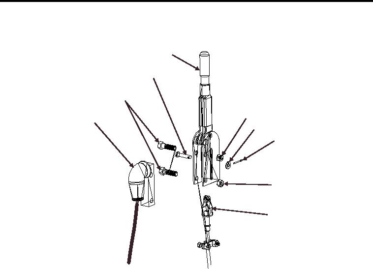
HAND BRAKE LEVER - (CONTINUED)
1
9
8
2
7
3
4
5
6
WP0079F2
Figure 2. Hand Brake Lever (Removal and Installation)
END OF TASK
INSTALLATION
1. Position switch assembly (Figure 2, Item 7) in hand brake lever.
2. Position hand brake lever on bracket.
3. Install two bolts (Figure 2, Item 8), two nuts (Figure 2, Item 2 and 5) securing hand brake lever to bracket.
4. Position hand brake cable (Figure 2, Item 6).
5. Install clevis pin (Figure 2, Item 9).
6. Install washer (Figure 2, Item 3) and secure with cotter pin (Figure 2, Item 4).
7. Perform hand brake adjustment this work package if necessary.
8. Remove wheel chocks.
9. Perform Maintenance Operation Check.
END OF TASK
END OF WORK PACKAGE
00883/blank