
0078
TM 1-1740-221-13&P&P
BRAKE FRICTION PLATES (FRONT AXLE) - (CONTINUED)
10. Remove spine axle rod assembly (Figure 1, Item 7) from the axle housing, which includes three friction
plates (Figure 1, Item 11), four counter plates (Figure 1, Item 10), plate carrier gear (Figure 1, Item 9) and
snap rings (Figure 1, Item 8 and 12).
11. Remove snap ring (Figure 1, Item 12).
12. Remove 3 friction plates (Figure 1, Item 11) and 4 counter plates (Figure 1, Item 10).
WP0069F2
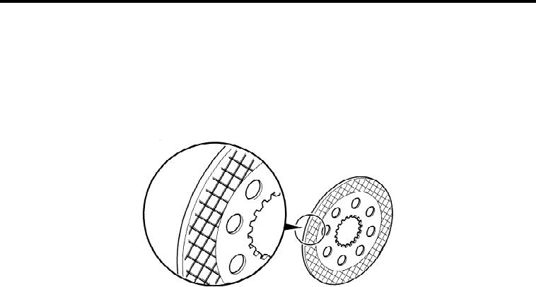
Figure 2.
Friction Pad Wear
NOTE
The brake pack comprises three friction plates and four counter plates. There are two counter
plates (Figure 1, Item 10) one at each end of the brake pack, which are not secured to the plate
carrier (Figure 1, Item 9). If plates are to be reused note position, reinstall plates in same order.
Inspect friction plates for wear (Figure 2). If the grid pattern is no longer visible they need to be
replaced. Replace all counter plates and friction plates as an assembly.
13. Remove four cap screws (Figure 1, Item 3).
14. Carefully remove differential housing plate (Figure 1, Item 2), 2 position pins (Figure 1, Item 4) (one not
shown) from the differential housing (Figure 1, Item 1). Clean differential mating surfaces.
NOTE
Heating differential housing (Figure 1, Item 1) at bolt thread location will aid in the removal
of mount bolts (Figure 1, Item 6).
15. Remove broken bolts.
16. Apply loctite 574 on mating surface of differential housing plate (Figure 1, Item 2).
17. Install differential housing plate (Figure 1, Item 2).
END OF TASK
00783