
0079
TM 1-1740-221-13&P&P
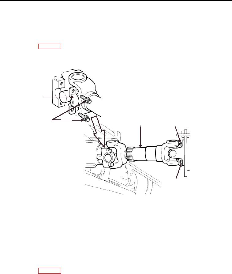
DRIVE SHAFTS - (CONTINUED)
4.
Install 4 u-joint mount bolts (Figure 1, Item 2) (2 not shown) and tighten. Torque to 55-63 ft. lbs..
5.
Position rear of front drive shaft at the front transmission output yoke lange.
6.
Install 4 bolts and nuts (Figure 1, Item 4) (2 not shown) and tighten. Torque to 33-38 ft. lbs..
7.
Lower vehicle (WP 0029).
8.
Perform Maintenance Operation Check.
1
4
2
3
3
WP0070F2
Figure 2. Rear Drive Shaft (Removal and Installation)
REAR DRIVE SHAFT
1. Position front of rear drive shaft (Figure 2, Item 2) at the transmission brake disc.
2. Install 4 bolts and nuts (Figure 2, Item 3) (2 not shown) and tighten. Torque to 33-38 ft. lbs..
3. Position rear of rear drive shaft at the rear differential.
4. Position 2 u-joint slip clamps (Figure 2, Item 1) (1 not shown).
5. Apply locktite 262 to the mount bolt threads.
6. Install 4 u-joint slip clamp bolts (Figure 2, Item 4) (2 not shown) and tighten. Torque to 55-63 ft. lbs..
7. Lower vehicle (WP 0029).
8. Perform Maintenance Operation Check.
END OF TASK
END OF WORK PACKAGE
00793/blank