
0079
TM 1-1740-221-13&P&P
DRIVE SHAFTS - (CONTINUED)
FRONT DRIVE SHAFT
1
2
4
3
WP0070F1
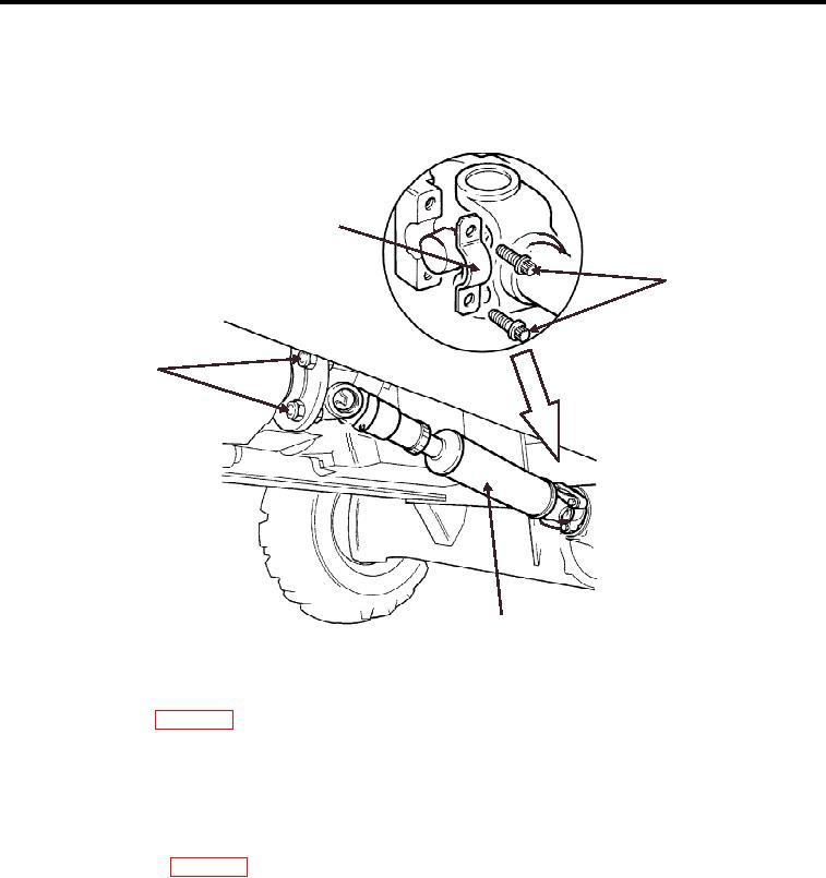
Figure 1. Front Drive Shaft (Removal and Installation)
1.
Lift vehicle front (WP 0029).
2.
Remove 4 nuts and mount bolts (Figure 1, Item 4) (2 not shown) and lower drive shaft.
3.
Remove 4 u-joint slip clamp bolts (Figure 1, Item 2) (2 not shown).
4.
Remove 2 u-joint slip clamps (Figure 1, Item 1) (1 not shown).
5.
Remove front drive shaft (Figure 1, Item 4).
REAR DRIVE SHAFT
1. Lift rear of vehicle (WP 0029).
2. Remove 4 nuts and mount bolts (Figure 2, Item 3) (2 not shown) and lower drive shaft.
3. Remove 4 u-joint slip clamp bolts (Figure 2, Item 4) (2 not shown).
4. Remove 2 u-joint slip clamps (Figure 2, Item 1) (1 not shown).
5. Remove rear drive shaft (Figure 2, Item 2).
END OF TASK
INSTALLATION
Front Drive Shaft
1. Position front of drive shaft (Figure 1, Item 3) at the front differential.
2. Position 2 u-joint slip clamps (Figure 1, Item 1) (1 not shown).
3. Apply locktite 262 to the mount bolt threads.
00792