
TM 1-1500-204-23-11
Figure 7-54. Process Flow Diagram for Potting
Fastener Hole Repair
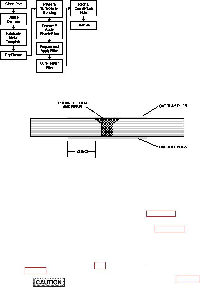
Figure 7-55. Potted Fastener Hole Repair
(1) Facilities, Equipment and Material. The
components. Use only water or water based
following equipment and materials are required: Vac-
materials. Disbonds may result and loss of
uum Cleaner, HEPA Filter, Marking Pen, Weights, Shot
structural integrity may occur.
Bags, Clamps, Drill Motor, 2000 RPM, Drill Guide,
(b) Inspect damaged fastener hole for
Drill Bit, Countersink Cutter, Piloted, Microstop Cage,
delaminations using NDI according to
Silicon Carbide Abrasive Paper, Wiping Cloth, Spat-
paragraph 5-2 and the system speciic
ula, Adhesive, Liquid (See System Speciic Technical
technical manual. If delaminations are
Manual), Vacuum Bag Repair Materials Kit, Fabric
present, irst repair the delaminations
(See System Speciic Technical Manual), Aluminum
per paragraph 7-10f.
Sheet Stock, 0.063 inches or thicker (Local Pro-
curement), Cotton Tipped Applicator, Solvent, Flash
(c) Remove NDI couplant by wiping with
breaker Tape, Mylar.
clean, water moistened wiping cloth.
(2) Potting Fastener Hole Repair Procedure.
(d) Fabricate Mylar Template.
(a) Remove dirt, grease and aircraft luids
Establish the centerline of the fas-
1
from repair area as described in para-
tener hole using reference points
and lines marked on the part as
shown in igure 7-52, using a per-
manent ink marking pen. Ensure
the reference points are far enough
DO NOT use oil or oil based materials
away from the fastener hole to not
as NDI couplants on advanced composite
be affected by the repair process.