
TM 1-1500-204-23-11
7-10. FASTENER HOLE REPAIR. The following pro-
180 grit sandpaper, see paragraph 6-3
cedures are used to repair damaged fastener holes in
for paint removal steps. Abrade 1 inch
load-bearing structures. Materials and repair details
beyond the hole.
are described in system speciic technical manuals.
If speciic repair materials are not identiied, match
(c) Dry the repair area to remove subsur-
the repair to the existing structure (i.e., carbon repair
face moisture per paragraph 6-5.
on carbon structures).
(d) Determine the hole size. For non-round
a. Fastener Repair. This procedure is used to
holes, determine the maximum width of
remedy small punctures or incorrectly located fastener
the damage.
holes in a composite laminate. This repair procedure
is not necessarily applicable to a particular weapon
system. The applicability of this repair depends
upon additional factors such as loading conditions
and laminate thickness. Consult the system speciic
Installation of an aluminum fastener is pro-
technical manual or engineering for further guidance.
hibited in carbon iber laminates.
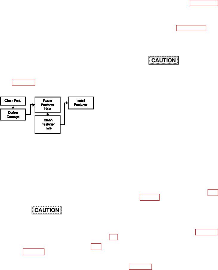
Refer to igure 7-49 for the Process Flow Diagram
for Fastener Repair.
(e) Select a repair fastener according to
the system speciic technical manual.
The repair fastener diameter should be
slightly larger than the damaged/mislo-
cated hole.
(f)
Ream the damaged/mislocated hole
true and round for the diameter of the
repair fastener.
(g) Vacuum to remove sanding and ream-
ing residue.
Figure 7-49. Process Flow Diagram for Fastener
Repair
(h) Using cotton-tipped applicators and
solvent, clean the reamed hole and
(1) Facilities, Equipment and Materials. The
abraded part surface(s). Thoroughly
following equipment and materials are required: Vac-
clean these areas with repeated wiping
uum Cleaner, HEPA Filter, Fastener Installation Equip-
until no residue is left on the applica-
ment, Drill Motor, 2000 RPM, Drill Guide, Drill Bit, Sil-
tors. Allow the solvent to evaporate for
icon Carbide Abrasive Paper, Solvent, Cotton Tipped
30 minutes.
Applicator, Fastener (See System Speciic Technical
Manual).
(i)
Install repair fastener according to para-
(2) Fastener Repair Procedure.
b. Countersink Repair. This procedure is limited
to oversized, elongated, or damaged fastener hole
countersink areas only. Oversized, elongated, or
Distance of repair fastener from adjacent
damaged countersinks that involve the fastener hole
fasteners and substructure shall be a minimum
in addition to the countersink area must be repaired
of two times the diameter of the repair fastener.
using one of the methods provided in paragraphs
7-10d,7-10e, 7-10g, or 7-10h. This repair procedure
(a) Remove dirt, grease and aircraft luids
is not necessarily applicable to a particular weapon
from repair area as described in para-
system. The applicability of this repair depends
upon additional factors such as loading conditions
and laminate thickness. Consult the system speciic
(b) Lightly abrade the surface area around
technical manual or engineering for further guidance.
the entrance (and exit if possible) of the
Refer to igure 7-50 for the Process Flow Diagram
puncture or fastener hole with 150 to
for Countersink Repair.