
TM 1-1500-204-23-11
3
If no delamination exists after
repair, or delamination is within
system speciic technical manual
limits for negligible damage, rein-
ish per step (p) below.
(p) Reinish.
Sand the area smooth with 180 grit
1
abrasive paper. Vacuum the sand-
ing dust from repair area. Wipe with
clean, dry wiping cloth.
Apply inish system in accordance
2
with paragraph 7-13b or the system
speciic technical manual.
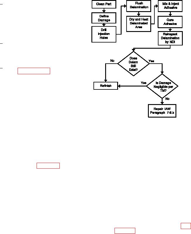
g. Resin Injection For Edge Delamination Repa-
ir. The following describes a positive pressure resin
injection repair process for edge delaminations on
solid laminates. This process only works where the
damaged area is clearly deined and where airlow
out of the panel edge is possible. The procedure
requires positive airlow through the delaminated area.
A clamping device is typically used for pressure dur-
ing cure; the resin being injected can be illed with
Figure 7-37. Process Flow Diagram for
micro-balloons to ensure adequate resin remains in
Delamination Open to an Edge Repair
the injected area during clamp-up. This repair tech-
nique usually applies to damages between 1/2 and 4
(1) Facilities, Equipment and Materials. The
inches in size. The applicability of this repair depends
following equipment and materials are required: Pres-
upon additional factors such a
sure Regulator, Heat Lamp, Vacuum Cleaner, HEPA
s loading conditions and laminate thickness. Consult
Filter, Drill Motor, 2000 RPM, Drill Stop (Common
the system speciic technical manual or engineering
Support Equipment), Twist Drill, Carbide, 1/8 Inch
for further guidance. Refer to igure 7-37 for the
Diameter, Temperature/Vacuum Controller, Injection
Process Flow Diagram for Delamination Open to an
Gun, Metallic Retainer Barrel, 2 1/2 Ounce, Clamps,
Edge Repair.
Backup Plate (local manufacture), Flash breaker Tape,
Solvent, Adhesive, Liquid (See System Speciic Tech-
nical Manual), Injection Cartridge, 2 1/2 Ounce, Dis-
posable, Injection Nozzle, Disposable, Silicon Carbide
Abrasive Paper, Wiping Cloth, Release Film.
(2) Resin Injection For Edge Delamination
Repair Procedure.
(a) Remove dirt, grease and aircraft luids
from repair area as described in para-